This thread has been locked.

If you have a related question, please click the "Ask a related question" button in the top right corner. The newly created question will be automatically linked to this question.

AWRL1432BOOST:AWRL1432BOOST LVDS layout guide

Part Number: AWRL1432BOOST
Other Parts Discussed in Thread: AWRL1432, , SN65LVDS31

Tool/software:

Layout guide not found in TI AWRL1432 and AWRL1432 BOOST file

Can provide AWRL1432BOOST LVDS layout guide file

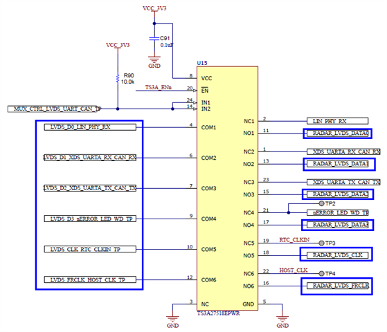
I want to know AWRL1432(radar) to TS3A27518(Switch) to SN65LVDS31(LVDS driver) to Connector , LVDS Trace length,width,Impedance,spacing layout guide

Thanks.

  • Hello,

    Thanks for your question.

    Hardware design checklist for AWRL1432 device based on AWRL1432BOOST EVM is under development and will be available on ti.com at AWRL1432 page shortly. Kindly refer the AWRL1432BOOST EVM layout until then for more details: https://www.ti.com/lit/zip/swrr183 

    The RDIF has four data lanes, one Bit Clock lane, and one Frame Clock lane. The trace lengths of all these lines should be tightly matched to each other to reduce delay mismatch and enable proper data communication. The following trace lengths have to be tightly matched

    • LVDS_D0, LVDS_D1, LVDS_D2, LVDS_D3, LVDS_CLK and LVDS_FRCLK have to be tightly matched between AWRL1432 and the inputs of TS3A27518EPWR(U15).
    • RADAR_LVDS_DATA0, RADAR_LVDS_DATA1, RADAR_LVDS_DATA2, RADAR_LVDS_DATA3, RADAR_LVDS_CLK and RADAR_LVDS_FRCLK have to be tightly matched between outputs of TS3A27518EPWR(U15) and the inputs of SN65LVDS31MDREP (U10, U14).
    • All the differential output signals from U10, U14 to connector have to be tightly matched. These Differential traces shall have an output impedance of 100ohms.

    Also, let us know if you need any additional details.

    Thanks. 

  • LVDS_D0, LVDS_D1, LVDS_D2, LVDS_D3, LVDS_CLK and LVDS_FRCLK have to be tightly matched between AWRL1432 and the inputs of TS3A27518EPWR(U15).

    →I want to know  AWRL1432 and the inputs of TS3A27518EPWR(U15) LVDS Trace length,Impedance spec,Thanks.

  • Hello,

    We do not have any trace length spec for the traces between AWRL1432 and inputs of TS3A27518EPWR(U15). These traces should be 50ohm impedance traces.

    Thanks.

  • Hello,

    AWRL1432 Radar Data InterFace (RDIF) is high-speed signal , for impedance  trace length no any require ?

  • Hello Willy,

    Apologies for the confusion before. As a good practice, it is recommended to match these single ended trace impedance to 50Ohms.

    Since the impedance is not dependent on trace length here. There is no spec for trace length. Regarding the trace width, this depends on the stack up used.

    Thanks.