This thread has been locked.

If you have a related question, please click the "Ask a related question" button in the top right corner. The newly created question will be automatically linked to this question.

AWR2944: Can't Flash due to QSPI_D1 can't pullup

Part Number: AWR2944
Other Parts Discussed in Thread: UNIFLASH,

Tool/software:

Hi, Gurus,

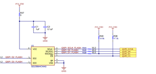
I almost copied AWR2944EVM design, i.e. PROC113D version. I changed the flash IC to GD25Q64EWIGR.

But I can't flash firmware, the Uniflash error is as following.

I tested the voltage of flash IC, and found  QSPI_D1 DC voltage is 2.4V, although I used a 10K pullup to 3V3_VIO.

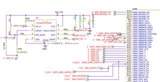
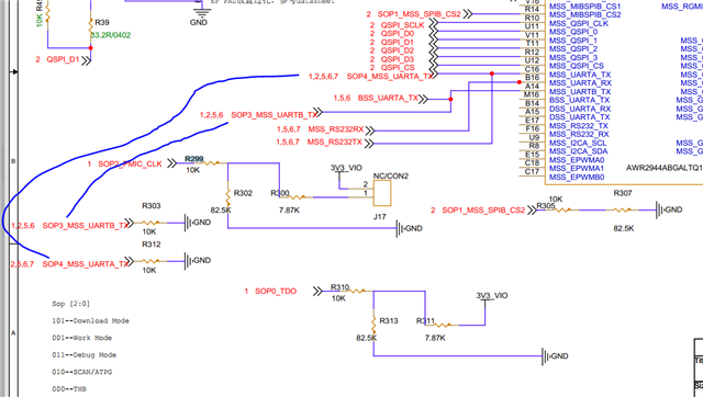
I used omnimeters to find that V11 pin of AWR2944 has a resistor to GND, and the resistor is about 20K--40K. So that QSPI_D1 DC voltage is dropped down to 2.4V.

I want to know how to set V11 pin to high-Z before flash? Or any other solution?

Best,

Tony Liu

PS: Flash Error message:

[2024/8/21 下午2:34:22] [INFO] Cortex_R5_0: Initialization complete.
[2024/8/21 下午2:34:22] [INFO] Cortex_R5_0: Sending UART Uniflash image at location C:\ti\uniflash_8.6.0\deskdb\content\TICloudAgent\win\ccs_base\mmWave\gen2/images/sbl_uart_uniflash.release.tiimage
[2024/8/21 下午2:34:41] [ERROR] Cortex_R5_0: XMODEM send failed, no response OR incorrect response from EVM OR cancelled by user, power cycle EVM and run this script again !!!
[2024/8/21 下午2:34:41] [INFO] Cortex_R5_0: UART Uniflash image sent.
[2024/8/21 下午2:34:41] [INFO] Cortex_R5_0: Sending SBL image at location E:/Fangjiajia/TDM/sbl_qspi.release.tiimage
[2024/8/21 下午2:34:51] [ERROR] Cortex_R5_0: XMODEM send failed, no response OR incorrect response from EVM OR cancelled by user, power cycle EVM and run this script again !!!
[2024/8/21 下午2:34:51] [ERROR] Cortex_R5_0: XMODEM recv failed, no response OR incorrect response from EVM OR cancelled by user,Power cycle EVM and run this script again !!!
[2024/8/21 下午2:34:51] [INFO] Cortex_R5_0: SBL image sent
[2024/8/21 下午2:34:51] [INFO] Cortex_R5_0: Sending Appimage at location E:/Fangjiajia/TDM/awr2944_corner_radar_921600_points.appimage
[2024/8/21 下午2:34:51] [ERROR] Cortex_R5_0: XMODEM send failed, no response OR incorrect response from EVM OR cancelled by user, power cycle EVM and run this script again !!!
[2024/8/21 下午2:34:51] [ERROR] Cortex_R5_0: XMODEM recv failed, no response OR incorrect response from EVM OR cancelled by user,Power cycle EVM and run this script again !!!
[2024/8/21 下午2:34:51] [INFO] Cortex_R5_0: Appimage sent
[2024/8/21 下午2:34:51] [INFO] Cortex_R5_0: Instance deinitialized!

  • Even I remove R39, the QSPI_D1 voltage is still 2.4V. So it is not relevant to Flash IC.

  • Hello,

    Why do you assume the pullup is the issue? We have the same on the EVM and have never had any issue.

    Can you confirm which pins you are using to flash?

    Does your board have XDS110 or how are you connecting to the PC?

    What is the SOP mode you are using?

    Did you confirm the device is booting up correctly by measuring VBGAP to make sure it is at 0.9V and XTAL to make sure it is running at 40MHz? Have you done all impedance checks and voltage checks to make sure power supplies and everything else is as expected on your board?

    Regards,

    Adrian

  • Hi, aozer,

    VBGAP=0.886V.

    XTAL shoule be tested later. We use the same pin as  PROC113D, as the following picture.

    But sorry, we don't use XDS110, is this the point caused the issue?

    We use FT232 IC to covert TTL to link to PC.

    Thanks for the reply.

    And I am looking forward to your reply as soon as possible.

    Best,

    Tony Liu

  • Hello,

    No, XDS110 is not required. You can also use a USB to UART converter.

    How are you configuring the SOP0,1,2,3,4 pins? How are you controlling radar NRESET?

    Please check all voltage levels and XTAL operation before moving to flashing. Please follow the HW bringup guidelines in the below hardware design checklist to check out the board before trying functional tests. After you have verified the board is working as expected then you can move to the flashing issue. I have highlighted the most important items below.

    https://www.ti.com/lit/zip/sprad30 

    Regards,

    Adrian

  • Hi, Adrian,

    I asked the vendor of crystal to test the XTAL, XTAL is OK.

    But SOP2 is 1.7V, while SOP1=0V and SOP0=3.1V.

    I removed R299, then SOP2=0V.  SOP are set as following.

    Meanwhile, SOP4 is pullup to 3V3 with a 100K resisitor. I replaced the pullup resistor to 510K, the SOP2 is still 1.7V.

    SOP2 1.7V is not from 2944.U18 pin (1.8V), because U18= 1.79V, not 1.7V. And when I removed R299, then SOP2=0V.

    So I don't know how SOP2 is 1.7V?

    I tested with two boards, which are manufactured by different PCB vendor, both SOP2=1.7V.

    I am looking forward to your reply as soon as possible.

    Best,

    Tony Liu

  • Hi, Adrian,

    Is it possible to review my schematic file by yourself?

    My email address is: thliu@linpowave.com

    Thank you very much.

    Best,

    Tony Liu