This thread has been locked.

If you have a related question, please click the "Ask a related question" button in the top right corner. The newly created question will be automatically linked to this question.

IWRL6432BOOST: Capture RAW ADC DATA from IWRL6432BOOST + DCA1000 using mmWave Studio 4.1.0.6.

Part Number: IWRL6432BOOST
Other Parts Discussed in Thread: IWRL6432, IWR6843, MMWAVE-L-SDK

Tool/software:

Hi!


I attempt to capture RAW ADC DATA from IWRL6432BOOST + DCA1000 using mmWave Studio 4.1.0.6.

In 'Connection' window I get Connected status. However when I try to use 'DCA Start Record' in 'SensorrConfig' I get:


''

No LVDS data

No Header

Record stop is done successfully"

in Output window.


While in RDIF CTRL I get API Status:
Failed: -103


  • Could you advice what to do in this case?

  • Hi

    Thanks for your query. Please allow us a couple of days to respond.

    Regards

  • Hello,

    No LVDS data can happen when your chirp parameters are set in a way that are invalid which prevents the sensor from starting.

    Try using a default configuration via loading LUA scripts for configuring and capturing. We have these two scripts within our Radar Toolbox in the TI Developer Zone. Once downloaded, find it within <RADAR_TOOLBOX>\tools\scripts\mmWaveStudio_luaExamples

    Best Regards,

    Pedrhom

  • Thank you so much! It helped and I finally got adc_data.bin file!


    I have additional question.
    I used radar_toolbox_2_20_00_05 where I found two <.lua> files:


    1.     IWRL6432_common_device_setup.lua

             As far as I understand it is used to configure "Connection" window of mmWave studio. Am I right?

    2.      IWRL6432_capture.lua

             I used it to configure "SensorConfig" window and get adc_data.bin.

    But I see that Freq Start (GHz) = 80 in this setup. And application does not provide any error! How is it possible when IWRL6432 works with 60 GHz range?


    And what is the proper following of actions which will change the Freq Start?
    I tried to initially change the frequency range in "Board configuration" and then changed the "Freq Start (GHz)", but got

    "No LVDS data"

    in output.

    So I confused.

  • Hello,

    I believe what is happening is that when you run the LUA script, the choices in the drop down boxes and fields of mmWaveStudio do not update as the LUA script sends the appropriate commands directly to the device. If you check IWRL6432_capture.lua line 30, you will see:

    Also your interpretation of the two scripts are correct.

    Best Regards,

    Pedrhom

  • Thank you so much, Pedrhom! 

    I checked. The frequency in the LUA script is really correct! 

    While investigating LUA script also some misunderstandings happened: 

    1.  I see LUA script that
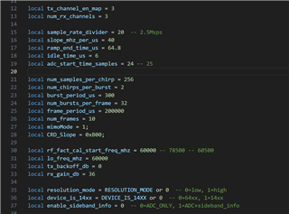
    local tx_channel_en_map = 3
    however, the total number of transmitters of IWRL6432 is 2, not 3. Can you explain it please? 

    2. Let us consider the example of default parameters in «IWRL6432_capture.lua»:
    local tx_channel_en_map = 3
    local num_rx_channels = 3local num_samples_per_chirp = 256
    local num_chirps_per_burst = 2
    local num_bursts_per_frame = 32
    local num_frames = 10

    When I use matlab script «read_adc_data_tx1tx2_lowPowerDevice.m»,
    what parameters should I place as an input to the function:

    n_rx_chan = ?
    n_tx_chan = ?
    n_samp_per_chirp = 256;
    n_chirps_per_frame = ?
    n_frames = 10;

    Best regards,
    Grigor Mardiyan

  • Hello Grigor,

    1. Definitely confusing, especially since num_rx_channels is a basic counter set to 3. If you notice for TX, it is not "number of tx channels" (like num_rx_channels) but "tx channel enable map" (tx_channel_en_map). The way this works is a binary mapping, where every bit will enable the respective TX.

    For example: enable TX1 = 01 = 1. enable ONLY TX2 = 10 = 2, enable TX1 and TX2 = 11 = 3. If this device had 3 TXs similar to IWR6843; then enable TX1, TX2, TX3 = 111 = 7

    2. With:

    local tx_channel_en_map = 3
    local num_rx_channels = 3
    local num_samples_per_chirp = 256
    local num_chirps_per_burst = 2
    local num_bursts_per_frame = 32
    local num_frames = 10

    It will be:

    n_rx_chan = 3
    n_tx_chan = 2
    n_samp_per_chirp = 256;
    n_chirps_per_frame = numChirpInBurst*numBurstInFrame/n_tx_chan = 2 * 32 / 2 = 32
    n_frames = 10;

    I hope you have noticed you should not be running read_adc_data_tx1tx2_lowPowerDevice.m directly, but rather in that same folder using dataPostProc_lowPowerDevice.m which calls the function in read_adc_data_tx1tx2_lowPowerDevice.m

    Best Regards,

    Pedrhom

  • Dear Pedrhom,

    Thank you very much for the answers!

    I am also interested:
    n_chirps_per_frame = numChirpInBurst*numBurstInFrame/n_tx_chan
    Am I right that it is for TDM case?

    Could you say please, how to calculate
    n_chirps_per_frame for BPM case?

  • Another unclear feature.

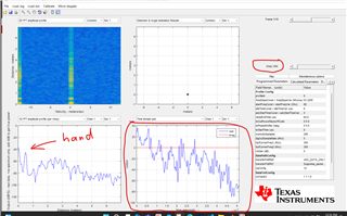
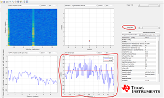
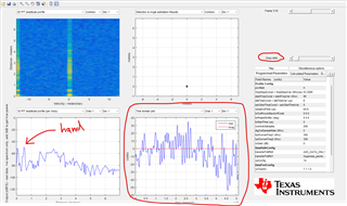
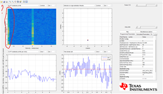
    There is an example of signal captured from my hand placed instead of radar.

    I use PostProc app and I see the peak of reflected signal just in case of even number of a chirp. In case of odd - no presence of a signal. I attached two pictures of it.

    Could you please advice what does this phenomenon mean?

    Radar parameters are:

    local tx_channel_en_map = 3
    local num_rx_channels = 3

    local sample_rate_divider = 60
    local slope_mhz_per_us = 45
    local ramp_end_time_us = 80
    local idle_time_us = 6
    local adc_start_time_samples = 5

    local num_samples_per_chirp = 128
    local num_chirps_per_burst = 2
    local burst_period_us = 260
    local num_bursts_per_frame = 256
    local frame_period_us = 67000
    local num_frames = 150
    local mimoMode = 1;
    local CRD_Slope = 0xB00;

    local rf_fact_cal_start_freq_mhz = 60000
    local lo_freq_mhz = 60000
    local tx_backoff_db = 0
    local rx_gain_db = 36

    local resolution_mode = RESOLUTION_MODE or 0
    local device_is_14xx = DEVICE_IS_14XX or 0
    local enable_sideband_info = 0


    Best regards,
    Grigor Mardiyan
           
  • And another question. I had a problem with matchind RAW data processing with the results of 1D FFT in PostProc.

    Then I found support answer:
    AWR1243: dBFs scaling in Radar Studio Post Processing in complex 1x, complex 2x and real mode - Sensors forum - Sensors - TI E2E support forums

    Could you say is it actual for the case of IWRL6432BOOST + DCA1000 ?

    If yes, could you say how to get window coefficients? Or I should apply them by myself?


    Best regards,
    Grigor Mardiyan

  • Hello Grigor,

    1. n_chirps_per_frame is the same for TDM vs BPM. For more information please see our MIMO Radar App note. For a quick skim, go to page 9.

    https://www.ti.com/lit/swra554

    2. With the chirp 3 being bad, I'd have to get more information. Does this happen every frame? Does every frame have at least one bad chirp? Could you try changing frame_period_us to something like 200000 to slow things down? Otherwise the configuration seems valid to me based on the timings used.

    3. We have MATLAB scripts with source code for IWRL6432 for converting raw data to 1D and 2D FFTs, it can be found in the MMWAVE-L-SDK directory below. You can use this to see exactly how the raw data is processed

    C:\ti\MMWAVE_L_SDK_05_05_00_01\tools\ADC_parser

    Best Regards,

    Pedrhom

  • "2. With the chirp 3 being bad, I'd have to get more information. Does this happen every frame? Does every frame have at least one bad chirp? Could you try changing frame_period_usto something like 200000 to slow things down? Otherwise the configuration seems valid to me based on the timings used."


    Yes, it happens every frame.


    I set frame_period_us = 200000.

    The result is the same. In every frame I see reflected peak just in chirps 1, 2, 4, 6, 8….


    Just in case, radar parameters are:

    local sample_rate_divider = 60

    local slope_mhz_per_us = 45

    local ramp_end_time_us = 80

    local idle_time_us = 6

    local adc_start_time_samples = 5


    local num_samples_per_chirp = 128

    local num_chirps_per_burst = 2

    local burst_period_us = 260

    local num_bursts_per_frame = 256

    local frame_period_us = 200000

    local num_frames = 150

    local mimoMode = 1;

    local CRD_Slope = 0xB00;


    local rf_fact_cal_start_freq_mhz = 60000

    local lo_freq_mhz = 60000

    local tx_backoff_db = 0

    local rx_gain_db = 36


    local resolution_mode = RESOLUTION_MODE or 0

    local device_is_14xx = DEVICE_IS_14XX or 0

    local enable_sideband_info = 0

  • Dear Pedrhom,


    1. When I launch default
    radar_toolbox_2_20_00_05\tools\scripts\mmWaveStudio_luaExamples\IWRL6432_capture.lua


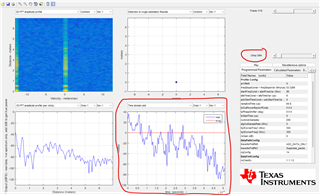
    I see the reflected signal from my hand in every chirp, however I also see that the appearance of signal changes systematically from chirp to chirp. It is different for odd and even number of a chirp. Below you can find pictures for 1, 2, 3, 4 chirp.

    Is it ok? How to axplain it?


    2. Another question. I see signal on the left side of 2d FFT, i.e. signal on negative velocity.


    There is no object which are moving with such speed. Just my hand in front of radar. How to explain it?


    Best regards,
    Grigor Mardiyan

  • Dear Pedrhom,


    Also I found out that do not see parameter in mmWave Studio, which lets to change Tx Output Power.
    I tried to change tx_backoff_db, but do not see any influence on recieved signal (1D FFT).


    Could you please advice how to change Output Power for IWRL6432BOOST + DCA1000 + MmWave Studio 4.1.0.6 ?


    Best regards,
    Grigor Mardiyan

  • Dear Pedrhom,


    I tried to use file C:\to\MMWAVE_L_SDK_05_05_00_01\tools\ADD_parser\ar_convertAdcData_xWRLx432.m ,

    which you recommended. It seems that it works correctly and there are no such problems which I see in mmWave studio. So further I will work with ar_convertAdcData_xWRLx432.m.


    P.S.
    Initially I tried read_adc_data_tx1tx2_lowPowerDevice.m, it did not provide adequate data.

    Best regards,
    Grigor Mardiyan

  • Hello Grigor,

    Just to confirm, using the same exact .bin data you saw the chirp issue that occurs every other chirp with mmWaveStudio but not with the MATLAB script? This will help narrow things out a lot and potentially identify a bug with mmWaveStudio.

    Taking another look at your configuration, it may be due to BPM being enabled. Can you disable it by changing mimoMode and check mmWaveStudio again?

    Best Regards,

    Pedrhom

  • Hi Pedrhom,

    1. Yes. When I read bin file by means of ar_convertAdcData_xWRLx432.m and the do 1D FFT and 2D FFT by myself I get pictures without anomaly I      mentioned above. But 1D FFT and 2D FFT in mmWave studio look suspicious.


    2. I have 
    local mimoMode =

    in IWRL6432_capture.lua.

    Is it correspond to BPM or TDM?

    3. And I repeat my question:

    "

    Also I found out that do not see parameter in mmWave Studio, which lets to change Tx Output Power.
    I tried to change tx_backoff_db, but do not see any influence on recieved signal (1D FFT).


    Could you please advice how to change Output Power for IWRL6432BOOST + DCA1000 + MmWave Studio 4.1.0.6 ?

    "


    Best regards,
    Grigor Mardiyan

  • Hello Grigor,

    mimoMode = 1 should be TDM

    For tx_backoff_db, what values did you try? The firmware allows a backoff of up to 26dB, do you see no change even with higher values of TX backoff? What data are all the graphs/data you are comparing to check for differences?

    Best Regards,

    Pedrhom

  • Dear Pedrhom,

    This is the two cases. I see the same level of signal on the 0 range and approximately the same level on the 1.5 m where human is standing.

    1. tx_backoff_db = 0

    2. tx_backoff_db = 26

    Best regards,

    Grigor Mardiyan

  • Hi!

    You did not answer my question! Please.