Tool/software:
Dear TI experts,
We encountered an issue during the development of the AWR2243 cascaded version:
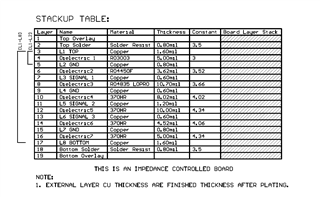
In the tidm464 layout of the AWR2243 Cascade, it is shown that the 20GHz LO strip line is connected to the GCPW Wilkinson power divider through a through-hole. I simulated the connection structure in HFSS using the size of the tidm464 layout and found that the impedance matching was poor (S11 was only -1.1dB).
For this situation, in SPRR407 (detailed schematic of design layout and components), it is written that "In the EVM design for SYNC trace transition being a blind via back drill was drom from TOP to L3". Here, it is said that the signal line transform via is formed as a blind hole through back drilling. Does the actual EVM use blind holes? If the through-hole is turned into a blind hole through back drilling, please provide reference back drilling size and back drilling stub length parameters?


