This thread has been locked.

If you have a related question, please click the "Ask a related question" button in the top right corner. The newly created question will be automatically linked to this question.

DRV425: Multiple DRV425RTJR in a single PCB

Part Number: DRV425

Tool/software:

Dear Team

I am planning to make a current sensor for pouch battery using DrV425.

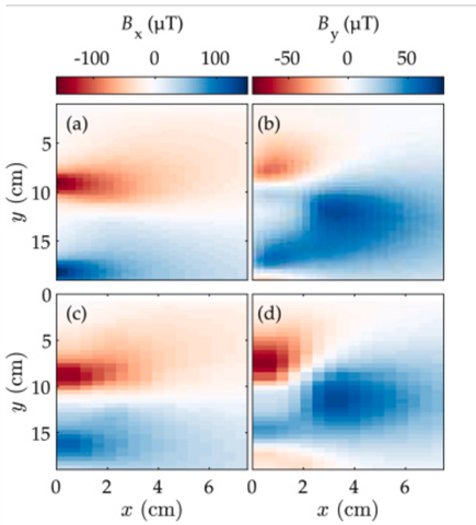
This paper is my reference.

In that paper the sensors are placed in a regular matrix form.(Please see Fig-1)

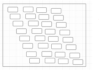
I am planning to place the sensor as shown below(Number of sensors is not finalized)

  1. May I know your thoughts about the placement ?
  2. How to decide the number of sensors?

  1. What are the hardware design considerations to be taken care when connecting multiple DRV425.
  2. Can I connect the output of all DRV425 together and Give to an ADC.I am planning to use ADC present in Arduno Nano.This is a sigle ended ADC
  3. Or do I need to keep a multiplexer and connect to ADC one  by one.

Kindly share your thoughts

  • Hello, 

    Thank you for your post. 

    This is a very interesting application. Unfortunately, I can only provide feedback and support for the DRV425 itself. For optimizations of this system, I would suggest reaching out to the authors of the article you linked. 

    For your last three questions here is my feedback:

    1. What are the hardware design considerations to be taken care when connecting multiple DRV425?
      1. Power consumption
        1. I would make sure that you provide enough power to the # of DRV425's that you use. You want to add the current at DRV1 and DRV2 outputs at full compensation range of 2mT and the IQ of the device. 
      2. Reference voltage of your system. 
        1. Make sure that the REF select is configured for your desired reference voltage output. You can have individual references and calibrate out the offset of each measurement. 
      3. You also want to make sure that you do not use magnetic components in your system as they will add offset to the DRV425 measurements. Also the Earth's magnetic field will also add some offset to your measurements. 
    2. Since each of these devices has an analog amplifier output, you cannot connect them together. All of the output stages you use will "fight" each other over their correct output voltage.
    3. For the type of system you are creating, I would recommend muxing the outputs for an accurate heat map. 

    I hope this helps,

    Joe

  • Hi Joe,

    Thank you very much.

    Since each of these devices has an analog amplifier output, you cannot connect them together. All of the output stages you use will "fight" each other over their correct output voltage.

    Does this means there is a variation in each amplifier output value and they will fight each other.Please correct me if I am wrong.

    Also the Earth's magnetic field will also add some offset to your measurements. 

    May I know any method to compensate this.

    I would recommend muxing the outputs for an accurate heat map

    Could you please tell me what you mean by accurate heat map

    You have any suggestion for MUX P/N

    Regards

    HARI

  • Hello Hari, 

    Does this means there is a variation in each amplifier output value and they will fight each other.Please correct me if I am wrong.

    This does not mean that there is variation that would be the cause of the issue. Say one of your DRV425s is sensing a high magnetic field and another DRV425 is sensing little to no magnetic field, then the first amplifier will want to reach close to its maximum output voltage. The second amplifier output stage will want to sit close to its 0 magnetic field output value (VREFIN). This will mean that one output stage is trying to reach 5V while the other is sitting at 2.5V. This will cause issues and it seems like the application that you are trying to recreate needs separate outputs. 

    May I know any method to compensate this.

    Please take a look at this thread for how to remove Earth's magnetic field: (+) DRV425: Nulling Earth's Magnetic Field - Sensors forum - Sensors - TI E2E support forums

    Could you please tell me what you mean by accurate heat map

    I am not an expert on your application but it looks like you need separate outputs. I would double check with the authors of your reference document. 

    You have any suggestion for MUX P/N

    I would suggest you reach out to the Mux team on the E2E forum for the best part recommendation. I am only familiar with out magnetic current sensors. 

    I hope this helps, 

    Joe

  • Hi Joe,

    Thank you very much.

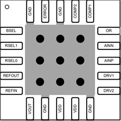
    I have a question regarding the via placement.(The vias shown in the thermal pad black color)

    • Do I need to use solder mask on these vias component side.?
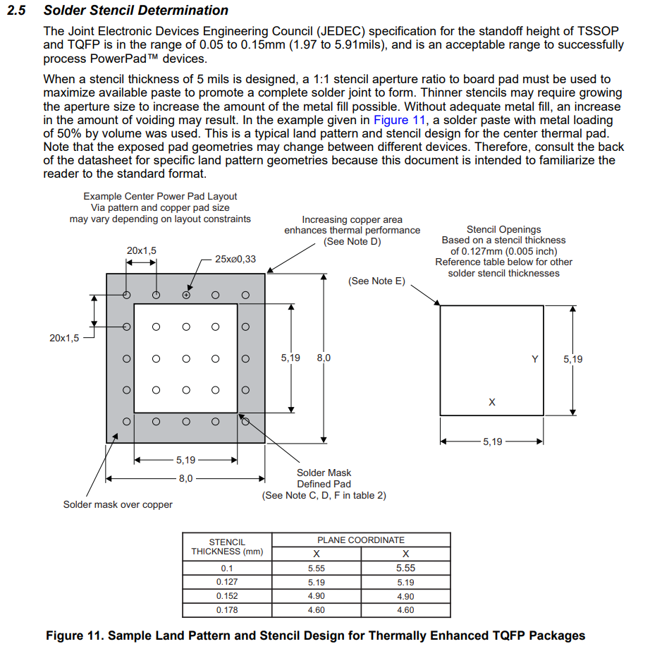
    • May I know the spacing between these vias

    Regards

    HARI

  • Hi Hari,

    Let me look into theae details and I will give you an update on Monday. 

    Thank you for your patience,

    Joe

  • Hello Hari, 

    You would place solder mask on these vias. 

    The most important thing for this package is to solder the exposed PowerPAD on the bottom of the package to the ground layer because the PowerPAD is internally connected to the substrate that must be connected to the most-negative potential.

    I believe that this app note on the PowerPAD technology and best practices for soldering and thermals should have more information on what you are looking for: https://www.ti.com/lit/an/slma002h/slma002h.pdf 

    I hope this helps,

    Joe

  • Hi Joe

    I have some questions regarding the layout guidelines.

    It says that

    "Common passive components and some PCB plating materials contain ferromagnetic materials that are magnetizable & Use nonmagnetic passive components (for example, decoupling capacitors and the shunt resistor) to prevent magnetizing effects near the DRV425."

    May I know can I use ceramic capacitors,Chip Resistors and FR4 pcb material?.

    Some SMT resistors and ceramic capacitors are non-magnetic, and some are not.

    Can you please suggest some other magnetic sensor IC's from TI which can be used for this application.

    Regards

    HARI

  • Hello Hari, 

    We do recommend non-magnetic components because the DRV425 is very sensitive. 

    Please use non-magnetic components for your design. 

    You can use a dedicated hall sensor and amplifier combination but this will present more noise compared to the DRV425. 

    For this reason, I still think that the DRV425 is suitable for your application. 

    Best Regards, 

    Joe