This thread has been locked.

If you have a related question, please click the "Ask a related question" button in the top right corner. The newly created question will be automatically linked to this question.

DRV5053: Help with understanding hall sensors for angular position measurement and calibration?

Part Number: DRV5053
Other Parts Discussed in Thread: TMAG5253, DRV5055,

Tool/software:

Hello, 

I am working on an angular position sensor solution using a TI DRV5053VAQDBZR and a TI XTR117AIDGKR 4-20mA Current-Loop Transmitter. I have been working from primarily the following TI resources: 

  1. Introduction to Hall-Effect Sensors
  2. Absolute Angle Measurements for Rotational Motion Using Hall-Effect Sensors
  3. Linear Hall-Effect Sensor Angle Measurement Theory, Implementation, and Calibration
  4. TI Magnetic Sense Simulator (TIMSS)

The objective is to measure angular position within ±15° (30 ° arc) with 0° as center. The hall sensor will output to the Current-Loop Transmitter which further outputs into an 12bit ADC. The design intention is to achieve about 1/10 of a degree measurement along the ±15° (30 ° arc). 

The mechanical setup is represented as follows: 
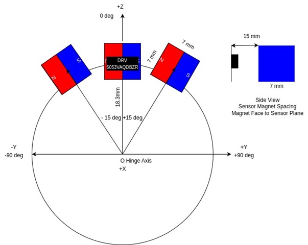
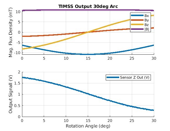
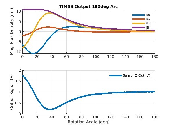
I have made myself familiar with TIMSS and replicated the mechanical/geometric setup above with the intended DRV5053VAQDBZR sensor powered with VCC=5V and assumed a N35 grade 7 x 7 x 7 mm magnet. The output of TIMSS for a 30 deg arc as well as a 180 deg arc result as follows:
I am confessedly out of my element as I have never worked with hall sensors and magnets at this level of design and would appreciate help, even criticism on part selections made thus far, with confusions I have from the above referenced documents. 

  1. The documents often suggest that measuring angular position with a single sensor is achievable but most of the examples or discussion seem to emphasizes two sensor rather than just one. Is there any reason why the selected hall sensor would not be a good choice for measuring angular position within the 30 deg range at the intended resolution? I am treating the 12 bit ADC as if I am only getting 8 bits out of it BTW.  
  2. I am unclear about the choice of magnet for this application. In some instances the documents suggest block magnets as "OK" for angular position but in other places suggest "diametric disc magnets". The best I can gather so far is that this may be related to the magnetic flux density *shape" from the magnet center line. To add to my confusion is that a cube magnet seems like it would be a better mechanical choice during installation compared to a disc magnet which is free to spin during instillation i.e. in cube case alignment of the magnet with the sensor is easier than the disc. Just how important or different would a cube or disc magnet choice be for this application? 
  3. The biggest confusion I have is on calibration. There are so may options in the implementation guide. I cannot peel away a good choice although the LUT method is most appealing so far I have been testing out the Peak Calibration Implementation but I get hung up on what to do since I want to limit my calibration to ±15° (30 ° arc). It seems like this method suggests that data must be collected on a ±90° (180 ° arc) for use with arcsin() but this seems like it would just complicate the code on the MCU/ADC side of the house. I am seem to think that on a ±15° (30 ° arc) I should be able to calibrate and expect better "sensor behavior" on such a limited range. Any help or guidance on the best way to calibrate that may lead to the adoption of Peak Calibration with LUT in our application would be appreciated. 

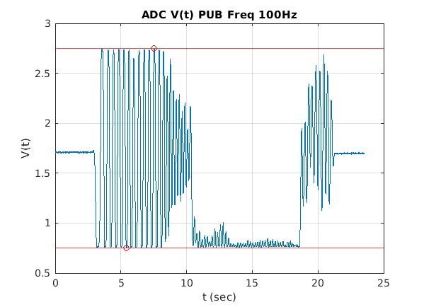
Here is example data collected from "manual excitation" of the mechanical system post current-loop transmitter. The plot shows 100Hz ADC data with a 16 sample average. My next steps are trying to calibrate the sensor correctly for the intended angular range. 
  • Wess,

    Thanks for reaching out on E2E.  It looks like you're off to a good start so far.  If you were to sweep you magnet farther on either side of your sensor in TIMSS you should see a more complete 'S' shaped curve.  Your 180 degree sweep shows the linear region where this configuration is mostly useful and the trailing end of half of that curve.  

    When operating in the linear region, there is no aliasing effect.  That is.. there is a 1:1 correlation between a voltage output and the mechanical position, but if you travel far enough you will pass the min or max peak, and then you have to find a way to resolve position from two possibilities.

    In the references where there are two sensors, the magnet is usually spinning on its own center.  In these cases, you should create a sinusoidal input for each sensor.  If you place them 90 degrees separated, you can derive angle using the arctangent calculation.

    In this case, your magnet and sensor are placed much further from the center of rotation, so you don't see quite the same behavior.  If you used two sensors, you could space them so that the linear regions overlap.  This is discussed in this app note:

    https://www.ti.com/lit/an/slya051b/slya051b.pdf

    The magnet you have chosen for this measurement is fine for this application.  For a 1D sensor this block magnet or a diametric disc magnet would both work since you need a horizontal polarization to create the Z component you need.  

    However, you may do just fine with a single sensor if it is possible to bring both the magnet and sensor closer to the axis of rotation.  By shortening the radius here, the total arc length traveled is reduced and you will be better able to limit motion to just the linear region for the sensor.

    The sensor you chose, DRV5053 is meant for high voltage applications, but generates a 2V peak output regardless of that supply.  We have other devices, DRV5055 or TMAG5253 which are ratiometric.  These devices will scale the magnetic sensitivity to match the supply voltage to help maintain an output that is a constant ratio of Vcc.  This can be helpful in battery operated systems where supply droop may affect an ADC reference voltage.

    If you can confine the result to the linear region, then you should already have a signal which varies linearly with respect to angle, but you might find that some more calibration is needed depending on your accuracy requirements.  You could better linearize the result if you are able to capture results at known positions. 

    Thanks,

    Scott

  • Hi Scott, 

    Thank you for the very helpful reply. If I may add our mechanical design has mechanical stops to limit the motion within the ±15° (30 ° arc). I am noticing my post and diagram may communicate a full 360° rotation however. As an additional clarification it seems like for our small 30° arc there is very little voltage change (within the linear region) which is making difficult to scale to our 4-20mA current transmitter but perhaps that is a different design part of the problem. Right now calibration to our small range is step 1.    

    Thank you for the additional app note. I will review it today and perhaps follow up or close the thread. 

    Thanks again, 

    Wess

  • Wess,

    Thanks for the details.  The linear section will typically be about as long as the length of the magnet.  So, if you position the magnet above the sensor such that 30 degrees correlates to an arclength that matches then you will have this portion of the problem simplified.

    Next, if you are not getting full use of the output range of the sensor, then you likely need a stronger magnetic field.  This can usually be helped by moving the sensor closer to the magnet or using a stronger magnet type.  The caution here though is that if you get very close to the magnet then the linear region will usually become distorted.  

    Thanks,

    Scott