


Tool/software:
Hello,
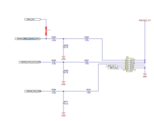
I have a question about the resistors connected to SOP terminal of IWR6843ISK.
Why are three resistors connected to each SOP terminal?
Could you please explain the purpose of each resistor?
Regards,
Kei
Tool/software:
Hello,
I have a question about the resistors connected to SOP terminal of IWR6843ISK.
Why are three resistors connected to each SOP terminal?
Could you please explain the purpose of each resistor?
Regards,
Kei
