Because of the Thanksgiving holiday in the U.S., TI E2E™ design support forum responses may be delayed from November 25 through December 2. Thank you for your patience.

AWR2544LOPEVM: AWR2544LOPEVM - Tx phase shifters in mmWave Studio

Part Number: AWR2544LOPEVM
Other Parts Discussed in Thread: AWR2544

Tool/software:

Hi everyone,

I am working on the AWR2544LOPEVM eval board with DCA1000 for data acquisition, which works well with FMCW/TDMA MIMO. This works well so far. Now I would like to configure the sensor for DDMA. In mmWave Studio there is the AdvChirpConf tab, in which I can set the Tx phase shifters via LUT and generate a file (AdvChirpLUTdata.txt). However, I cannot find any documentation on the format of this file. Do you have any information for me on what I have to set for a constant phase shift per Tx that increases linearly over the chirps and how the LUT text file is structured?

I also have a second question: mmWave Studio sends commands to the AWR via USB and controls the DCA1000 via Ethernet. Is it possible to get these commands so that I can send them directly, e.g. from python? This would avoid the "detour" via the mmWave Studio GUI, which is very practical for testing purposes, but is not necessary for operation (if the configuration is always the same).

Thanks for your reply!

Fabian

  • Hi Fabian,

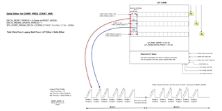
    Apologies for the delay. For your first query, you can consider LUT as a file which describes the fixed delta increment or unique dithers for each chirp parameters. for more details on LUT you can refer to section 19 of the following document - 

    mmwave_studio_03_01_03_01\docs\mmwave_studio_user_guide.pdf

    To understand the AdvChirpLUTdata.txt format better, once the configuration is done and the LUT file is generated, just compare and see the lut file against the configurations that you have done in the studio. basically, that file will have the offset, delta and few other parameters.

    For your second query, we don't have any script to send the commands directly to the device.

    Regards,

    Shruti

  • Dear Shruti,

    thank you for your response! For each TX, I can enter four values in mmWaveStudio. The documentation you recommended states that "four types of control can be achieved on each parameters of a chirp" and lists "3. Delta increment every N chirps: On top of sequence of unique chirps from LUT, the fixed delta increment can be done every N chirps." Is my assumption correct that I have to enter a phase value in the third row of the text fields shown in the screenshot below in order to achieve a fixed phase delta across the chirps of a frame? I would like to start with phase offset 0 for the first chirp in the frame, then have an offset of 1x, 2x, 3x (...) for chirps 2, 3, 4 (...) and start over with 0 again in the next frame.


    BR,
    Fab

  • Hi Fab,

    Here the fixed delta doesn't mean that you will get the constant phase between the N chirps. using the fields given in the studio gui you can fix some customizable fixed delta between the chirps.

    for example, if we configure the 4 rows for delta with the following phases 15, 35, 45, 70 degrees and suppose our reference/default phase is 90 degrees.

    then for the above case the first chirp will have 90+15, the next chirp will have 90+35, followed by 90+45 and 90+70 degrees of phase shift, if we have more number of chirps in the series the frame then this pattern will repeat i.e. again the next chirp will have 90+15.....90+70 degrees of phase shift.

    for your use case that you have mentioned, i.e. to have a phase shift like 1x,2x,3x for the continuous chirps, you can configure the fields with values like 30, 60,90 and so on...

    Hope this resolves your query.

    Regards,

    Shruti

  • Hi Fab,

    Here are additional inputs to AdvChirp, that I would suggest you to go over and have more understanding.

    mmwave_mcuplus_sdk_04_06_01_02/mmwave_dfp_02_04_14_00/docs/mmwave_dfp_user_guide.pdf (6.2 Advanced chirp configuration )

    Test application showcasing advChirp usage

    mmwave_mcuplus_sdk_04_06_01_02/mmwave_mcuplus_sdk_04_06_01_02/ti/control/mmwave/link_test/common/link_test.c  (MmwaveLink_rlSetAdvChirpCfg function)

    .

    Regards,

    Jitendra

  • Hi Jitendra,

    thank you for the additional information. Let me describe my steps:

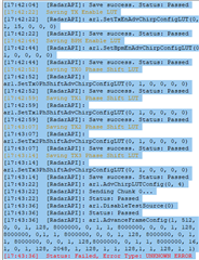
    I am using mmWaveStudio and I set up the connection as described in the documentation ("Connection" tab). In the "StaticConfig" tab, I activate "Adv Chirp conf En" and "Per Chirp Phase Shifter En" to activate the advanced chirp configuration. After configuring the tab "DataConfig" according to the documentation, I configure a profile in the tab "SensorConfig" and configure the frames separately in the "AdvFrameConfig" tab. The issue seems to come in the "AdvChirpCfg" tab: To set up my fixed delta phase shift in consecutive chirps, I choose the "Chirp Param Index" as "TX0_PHASE_SHIFTER" and apply a certain value for "SF0 Delta", since I'm only using a single subframe which spans the entire frame. However, when looking at my recorded data, the TX seems to be disabled even though I activate it in the "TX Enable" section by entering a "1", meaning to activate TX0 and confirming with the "Set" button in the section "Configure Device". I noticed that, no matter which of the ten individual chirp settings I try to change (Frequency Slope, Idle Time, ...), the resulting LUA-command is always the same (ar1.SetTx0PhShiftAdvChirpConfigLUT(0, 4, 0, 0, 0, 0) for a configuration with all-zeros). This behavior seems faulty to me since I would expect different commands to be sent for different settings. Also, this lacks documentation in the mmWaveStudio user guide.

    If it helps for debugging, I can also post my LUA script for applying all of the mentioned settings.

    Looking forward to your response!
    BR, Fab

  • Hi,

    Can you post your lua script as well. I think there is some configuration issue here, which we will need to evaluate via your script. 

    Thanks,

    Pradipta. 

  • Dear Pradipta,

    please find my script below.

    BR, Fab

    --------------------------------- STARTUP -------------------------------------
    ------------------------ DO NOT MODIFY THIS SECTION ---------------------------

    -- mmwavestudio installation path
    RSTD_PATH = RSTD.GetRstdPath()

    -- Declare the loading function
    dofile(RSTD_PATH .. "\\Scripts\\Startup.lua")

    ------------------------------ CONFIGURATIONS ---------------------------------

    -- RS232 COM Port number
    uart_com_port     = 10


    -- Tab Connection
    ar1.FullReset()
    ar1.SOPControl(2)
    ar1.Connect(uart_com_port,921600,1000)
    ar1.Calling_IsConnected()
    ar1.SelectChipVersion("AR1642")
    ar1.deviceVariantSelection("XWR2544")
    ar1.frequencyBandSelection("77G")
    ar1.SelectChipVersion("AWR2544")
    ar1.DownloadBSSFw("C:\\ti\\mmwave_studio_03_01_03_01\\rf_eval_firmware\\radarss\\xwr25xx_radarss_rprc.bin")
    ar1.GetBSSFwVersion()
    ar1.DownloadMSSFw("C:\\ti\\mmwave_studio_03_01_03_01\\rf_eval_firmware\\masterss\\xwr2xxx_masterss.bin")
    ar1.GetMSSFwVersion()
    ar1.GetBSSPatchFwVersion()
    ar1.PowerOn(0, 1000, 0, 0)
    ar1.RfEnable()

    -- Tab StaticConfig
    ar1.ChanNAdcConfig(1, 1, 1, 1, 1, 1, 1, 1, 2, 0, 0)
    ar1.RfLdoBypassConfig(0x0)
    ar1.LPModConfig(0, 0)
    ar1.SetMiscConfig(1, 1, 0, 0, 0, 0, 0, 0, 0, 0.4)
    ar1.RfInit()

    -- Tab DataConfig
    ar1.DataPathConfig(513, 1216644097, 0)
    ar1.LVDSLaneConfig(0, 1, 0, 0, 0, 1, 0, 0)

    -- Tab SensorConfig
    ar1.ProfileConfig(0, 77.100000018, 4, 1, 60, 0, 0, 0, 0, 0, 0, 0, 0, 15.981, 0, 2048, 42667, 2216755200, 0, 30, 0, 0, 0)

    -- Tab AdvChirpCfg
    ar1.AdvChirpConfig_mult(1, 0, 0, 0, 0, 0, 0, 0, 0, 0, 0, 0, 0, 1, 0, 0, 0, 0, 0)
    ar1.AdvChirpConfig_mult(1, 1, 0, 0, 0, 0, 0, 0, 0, 0, 0, 0, 0, 1, 0, 0, 0, 0, 0)
    ar1.AdvChirpConfig_mult(1, 2, 0, 0, 0, 0, 0, 0, 0, 0, 0, 0, 0, 1, 0, 0, 0, 0, 0)
    ar1.AdvChirpConfig_mult(1, 3, 0, 0, 0, 0, 0, 0, 0, 0, 0, 0, 0, 1, 0, 0, 0, 0, 0)
    ar1.AdvChirpConfig_mult(1, 4, 0, 0, 0, 0, 0, 0, 0, 0, 0, 0, 0, 1, 0, 0, 0, 0, 0)
    ar1.AdvChirpConfig_mult(1, 5, 0, 0, 0, 0, 0, 0, 0, 0, 0, 0, 0, 1, 0, 0, 0, 0, 0)
    ar1.AdvChirpConfig_mult(1, 6, 0, 0, 0, 0, 0, 0, 0, 0, 0, 0, 0, 1, 0, 0, 0, 0, 0)
    ar1.AdvChirpConfig_mult(1, 7, 0, 0, 0, 0, 5, 0, 0, 0, 0, 0, 0, 1, 0, 0, 0, 0, 0) -- introduce a phase shift for testing
    ar1.AdvChirpConfig_mult(1, 8, 0, 0, 0, 0, 0, 0, 0, 0, 0, 0, 0, 1, 0, 0, 0, 0, 0)
    ar1.AdvChirpConfig_mult(1, 9, 0, 0, 0, 0, 0, 0, 0, 0, 0, 0, 0, 1, 0, 0, 0, 0, 0)
    ar1.AdvChirpConfig_mult(1, 10, 0, 0, 0, 0, 0, 0, 0, 0, 0, 0, 0, 1, 0, 0, 0, 0, 0)
    ar1.ClearAdvChirpLUTConfig()
    ar1.SetProfileAdvChirpConfigLUT(0, 1, 0, 0, 0, 0)
    ar1.SetStartFreqAdvChirpConfigLUT(0, 1, 0, 0, 0, 0, 0, 0)
    ar1.SetFreqSlopeAdvChirpConfigLUT(0, 1, 0, 0, 0, 0)
    ar1.SetIdleTimeAdvChirpConfigLUT(0, 1, 0, 0, 0, 0, 0, 0)
    ar1.SetADCTimeAdvChirpConfigLUT(0, 1, 0, 0, 0, 0, 0, 0)
    ar1.SetTxEnAdvChirpConfigLUT(0, 1, 15, 0, 0, 0) -- enable all Tx
    ar1.SetBpmEnAdvChirpConfigLUT(0, 1, 0, 0, 0, 0)
    ar1.SetTx0PhShiftAdvChirpConfigLUT(0, 1, 0, 0, 0, 0)
    ar1.SetTx1PhShiftAdvChirpConfigLUT(0, 1, 0, 0, 0, 0)
    ar1.SetTx2PhShiftAdvChirpConfigLUT(0, 1, 0, 0, 0, 0)
    ar1.SetTx3PhShiftAdvChirpConfigLUT(0, 1, 0, 0, 0, 0)
    ar1.AdvChirpLUTConfig(0, 4)

    -- Tab AdvFrameCfg
    ar1.AdvanceFrameConfig(1, 512, 0, 0, 1, 128, 8000000, 0, 1, 1, 8000000, 0, 0, 1, 128, 8000000, 0,1, 1, 8000000, 0, 0, 1, 128, 8000000, 0, 1, 1, 8000000, 0, 0, 1, 128,8000000, 0, 1, 1, 8000000, 16, 1, 0, 1, 128, 256, 1, 128, 1, 1, 128,1, 1, 128, 1, 1)

    -- DCA1000 setup
    ar1.GetCaptureCardDllVersion()
    ar1.SelectCaptureDevice("DCA1000")
    ar1.CaptureCardConfig_EthInit("192.168.33.30", "192.168.33.180", "12:34:56:78:90:12", 4096, 4098)
    ar1.CaptureCardConfig_Mode(1, 2, 1, 2, 3, 30)
    ar1.CaptureCardConfig_PacketDelay(25)
    ar1.GetCaptureCardFPGAVersion()


    ---------------------------- Exit MMwave Studio --------------------------------
    --os.exit()

  • Hi Fab,

    This setting is incorrect as below. 

    ar1.ProfileConfig(0, 77.100000018, 4, 1, 60, 0, 0, 0, 0, 0, 0, 0, 0, 15.981, 0, 2048, 42667, 2216755200, 0, 30, 0, 0, 0)

    Here you are selecting VCO1 

    As per the ICD the frequency is be within 76 to 77 GHz only whereas your start frequency is over 77 GHz. 

    Also please refer to the ICD as well when configuring the Advance chirp parameters.

    Thanks,

    Pradipta.