This thread has been locked.

If you have a related question, please click the "Ask a related question" button in the top right corner. The newly created question will be automatically linked to this question.

AWR2944: Query on how TI RFE utilizes the programmed Rx Gain factory calibrations

Part Number: AWR2944

Tool/software:

The following figure is taken from TI monitoring application note (SPRACW7A) and I'm trying to understand the math that's used to generate the "25C Zeroed Out Gain Mismatch vs Temp "
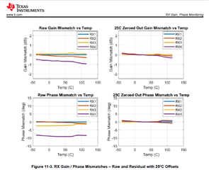
As far as I understand, the math for computing the Rx Gain absolute error per Rx channel is : | (measured Rx Gain of the channel - T0 Rx Gain of the channel) - Programmed Rx Gain |

but, this math doesn't seem to add up to the figure shown above and I've tried to explain this using an example below.

Programmed Rx Gain = 24dB.

Measured Rx Gain of the channel at time T0 = 23dB.

Measured Rx Gain of the channel at a later time = 22.5dB.

So, as per my understanding, the Rx Gain absolute error in this case should be = | (22.5 - 23) - 24 | = 24.5dB. But the "25C Zeroed Out Gain Mismatch vs Temp " indicates that the error will be closer to 0 upon compensating using the T0 values, so please provide your comments on this.

  • Hi Trilok,

    The math would be:

    absolute_error = |Measured RX gain of the channel - Programmed RX gain of the channel|;

    25C_offset = absolute_error @ 25C;

    error_after_zeroing_out = absolute error - 25C_offset

    Regards,

    James

  • Hi James,

    The suggested math above implies that the RX gain absolute error is essentially trying to detect "aging" errors of the receive channel's gain. It is incapable of detecting systematic errors in the receive channel's gain that could exist from the time of assembly of the device.

    For instance, if the device had a faulty LNA on a channel and even if the measured RX gain of the channel is way off of the programmed Rx gain, then the above math of computing the Rx gain absolute error will not detect this erraneous condition. Please let me know on ways of detecting such cases.

  • Hi Trilok,

    The idea of 'zeroing out' at 25C is to tighten the spread, so that only differences in the 'shape' of the curve vs. temperature create spread.  

    I understand your question.  For example, you are wondering about a part that has very high '25C_offset' and how subtracting this out may obscure an issue.  However, the RX gain error monitor will still be able to catch these gross errors.  

    Regards,

    James

  • Hi James,

    I don't understand how the following is true. 

    However, the RX gain error monitor will still be able to catch these gross errors.  

    I'm taking an example to explain the usecase of systematic errors (gross errors) : 

    Programmed Rx Gain = 24dB. Measured Rx Gain of the channel at time T0 = 14dB. Measured Rx Gain of the channel at a later time = 13.5dB.

    So, 25C_offset would be = 10dB. error_after_zeroing_out = 0.5dB. 

    The abolute gain error after zeroing out would look to be within the limits even if there were gross errors in the channel. So, assuming the relative gain error is not enabled and/or if the gross error is equally present in all the receive channels, then it seems to me that the Rx gain monitor will not be able to catch gross errors.

  • Hi Trilok,

    The RX gain monitor finds raw gain error (i.e. before zeroing offset).  However, we generally recommend that you use the absolute errors of each RX chain to calculate the relative zero-ed out gain error.  We then recommend that you set appropriate thresholds for each value, the absolute errors and the relative zero-ed out error.  The thresholds for the absolute errors should be wider than the thresholds for the zero-ed out relative errors. 

    Hope this helps!

    Regards,

    James 

  • Hi James,
    Could you please point me to the relevant document where I can see that the RX gain monitor finds raw gain error (i.e. before zeroing offset) ?

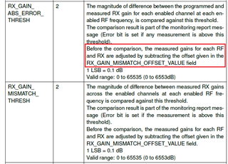
    I'm pasting a snippet from the mmWave Radar ICD's definition of "AWR_MONITOR_RX_GAIN_PHASE_CONF_SB" and it clearly states that the zeroing offsets are applied before the comparison is made to detect the Absolute gain error.

    Also, I think we should make sure we agree on the terminology, from what I understand from your earlier replies "absolute error" = |Measured RX gain of the channel - Programmed RX gain of the channel|. However, the "relative gain error" in my reply corresponds to the magnitude of difference between measure RX gains across the RX channels ( i.e. RX_GAIN_MISMATCH_THRESH is the above snapshot)

  • Hi Trilok,

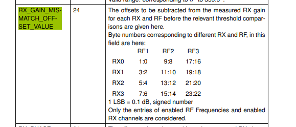
    As mentioned there, you have the ability to set the offset, so this is how you can e.g. use looser limits for a non-zeroed-out value, or tighter limits for a zeroed-out value (where for the zeroed out value you would set RX_GAIN_MISMATCH_OFFSET_VALUE to be whatever value is needed to zero-out the gain mismatch at 25C).  

    I don't quite follow what you mean by magnitude of difference between measured RX gains vs RX channels. To get that, I would think you would need to find the difference between the parts that have the highest and lowest offset.

    Please let me know if you have any other questions.

    Regards,

    James

  • Hi James,

    The math you've stated in this thread doesn't seem to comply with the behavior I see on my bench.

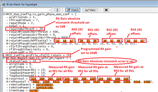
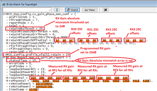
    I've tried to capture the key aspects in the snapshot below. In brief, I followed your math to zero-out the RX Gain errors using 25C offsets and my expectation then is that the RX Gain error threshold can have a tightened value, but this is not what I see on my bench. I see that the RX Gain absolute error status gets set for a threshold of 2dB (high enough after zeroing out) which suggests that the math used in the monitor might be different to what you've stated above? Please have a look at these numbers and provide your comments.

    Trilok

  • Hi Trilok,

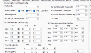
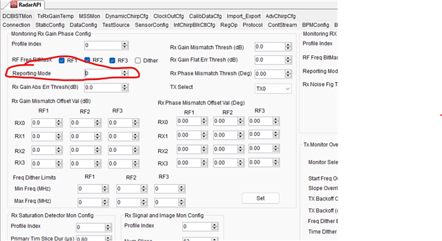
    You should be able to adjust the threshold to anything you like, e.g. if you want to lower it below 2dB you should be able to do that. e.g. in mmWave studio this is a configurable parameter:

    Please let me know if I have misunderstood your concern.

    Regards,

    James

  • Hi James,

    Let me rephrase my concern for better understanding : 

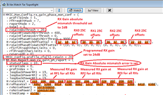
    I have tried to test the RX Gain monitoring on my test bench and I followed your suggestion to program the 25C offset values to zero out the mismatch. However, the RX Gain monitoring reports from the RFE is flagging an 'absolute gain mismatch error' which is not expected. This is the concern that I would like you to clarify. Please see below for evidence for this unexpected behavior : 

    Test Bench Result Snapshot:

    Test Bench Result Readings

    Programmed RX Gain = 24dB.

    RX Gain Errors at 25C as per your math:

    RX0 RF1 25C gain mismatch offset value = 1.7dB.

    RX0 RF2 25C gain mismatch offset value = 1.8dB.

    RX0 RF3 25C gain mismatch offset value = 1.7dB.

    RX1 RF1 25C gain mismatch offset value = 3.4dB.

    RX1 RF2 25C gain mismatch offset value = 3.5dB.

    RX1 RF3 25C gain mismatch offset value = 3.4dB.

    RX2 RF1 25C gain mismatch offset value = 3.6dB.

    RX2 RF2 25C gain mismatch offset value = 3.7dB.

    RX2 RF3 25C gain mismatch offset value = 3.6dB.

    RX3 RF1 25C gain mismatch offset value = 2.2dB.

    RX3 RF2 25C gain mismatch offset value = 2.3dB.

    RX3 RF3 25C gain mismatch offset value = 2.2dB.

    Raw RX Gain Errors as per your math:

    RX0 RF1 25C gain mismatch = 1.7dB.

    RX0 RF2 25C gain mismatch = 1.6dB.

    RX0 RF3 25C gain mismatch = 1.6dB.

    RX1 RF1 25C gain mismatch = 3.4dB.

    RX1 RF2 25C gain mismatch = 3.3dB.

    RX1 RF3 25C gain mismatch = 3.3dB.

    RX2 RF1 25C gain mismatch = 3.5dB.

    RX2 RF2 25C gain mismatch = 3.4dB.

    RX2 RF3 25C gain mismatch = 3.4dB.

    RX3 RF1 25C gain mismatch = 2.1dB.

    RX3 RF2 25C gain mismatch = 2.0dB.

    RX3 RF3 25C gain mismatch = 2.0dB.

    Zeroed-Out RX Gain Errors as per your math:

    Zeroed-Out RX0 RF1 25C gain mismatch = 0.0dB.

    Zeroed-Out RX0 RF2 25C gain mismatch = 0.2dB.

    Zeroed-Out RX0 RF3 25C gain mismatch = 0.1dB.

    Zeroed-Out RX1 RF1 25C gain mismatch = 0.0dB.

    Zeroed-Out RX1 RF2 25C gain mismatch = 0.2dB.

    Zeroed-Out RX1 RF3 25C gain mismatch = 0.1dB.

    Zeroed-Out RX2 RF1 25C gain mismatch = 0.1dB.

    Zeroed-Out RX2 RF2 25C gain mismatch = 0.3dB.

    Zeroed-Out RX2 RF3 25C gain mismatch = 0.2dB.

    Zeroed-Out RX3 RF1 25C gain mismatch = 0.2dB.

    Zeroed-Out RX3 RF2 25C gain mismatch = 0.3dB.

    Zeroed-Out RX3 RF3 25C gain mismatch = 0.2dB.

    So, per your math, the maximum Zeroed-Out RX gain error in the above test is 0.3dB. Then why is the TI RFE reporting a failure status for the RX Gain Absolute Error when the corresponding threshold is set to 2dB?

    Trilok

  • Hi Trilok,

    could you also include the error message?  Also, I believe its possible to ask the monitor to report regardless of the threshold, or only when the threshold is crossed.  Could you confirm that you have programmed it to report only when the threshold is crossed?

    Regards,

    James

  • Hi James,

    There is no error message. 

    Then why is the TI RFE reporting a failure status for the RX Gain Absolute Error when the corresponding threshold is set to 2dB?

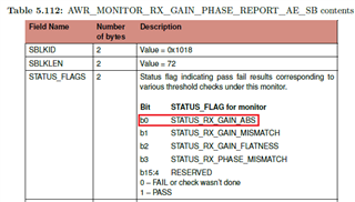
    What I mean by the above quoted text is that the host receives the monitoring report with STATUS_RX_GAIN_ABS bit (shown below) set to "0". And this is not expected. 

    In our application, we set the monitoring mode to "2" i.e. reports are sent every monitoring period with threshold check.

    Trilok

  • Hi Trilok,

    I understand now.  Just to confirm, if you set the threshold to 4 dB does that bit become 1?

    Regards,

    James

  • Hi James,

    In my tests, the threshold was set to 2dB and the bit becomes 1. 

    Trilok

  • Hi Trilok,

    1 means pass, so I think it is correct.  

    Regards,

    James

  • HI James,

    I made a typo in the following quoted text.

    In my tests, the threshold was set to 2dB and the bit becomes 1. 

    In my tests, the threshold was set to 2dB and the bit becomes 0 (you can see this in the below picture, i.e. the variable "RF_Mon_Report.mon_rx_gain_ph_report.statusFlags)

    I have not tried to find out at what threshold the bit becomes 1 as this is not my primary concern for now.

    Trilok

  • Hi Trilok

    I'm trying to understand what could be the problem.  If you see the bit become 1 when you set the threshold to 4 dB (since it looked like you non-zeroed out offsets are all less than that), it might be a clue as to what is going on.  Could you try changing the threshold and confirm that you see the bit go to 1? If that happens then I would suspect that there is some issue in how the offsets are being set.

    Regards,

    James

  • Hi James,

    I did some follow-up tests and the bit stays at 0 when the threshold is set to 4dB. The bit becomes 1 when the threshold is set to 7.5dB and above.

    I go back to what I said in my original post (quoted below) and I suspect that this is the math used to compute the Zeroed-Out RX Gain errors and not how you've stated. Please double check the math used (perhaps verify on your setup as well) and let me know your comments.

    As far as I understand, the math for computing the Rx Gain absolute error per Rx channel is : | (measured Rx Gain of the channel - T0 Rx Gain of the channel) - Programmed Rx Gain |

    Trilok

  • Hi Trilok,

    the 25C value would definitely correspond to 'Time 0' as generally we envision that value as being found at the factory.  in that case, the math is actually the same I believe:

    absolute_error = |Measured RX gain of the channel - Programmed RX gain of the channel|;

    25C_offset = absolute_error @ 25C (found in the factory) = 'T0 RX gain at 25C'

    error_after_zeroing_out = absolute error - 25C_offset = |Measured RX gain of the channel - Programmed RX gain| - 'T0 RX gain at 25C'

    | (measured Rx Gain of the channel - T0 Rx Gain of the channel) - Programmed Rx Gain |

    in other words, We basically recommend that you record inter channel gain mismatches at factory. Then in the field, look for deviations from those recorded values.

    Regards,

    James

  • Hi Trilok,

    sorry I understand a bit better the source of confusion now.  

    I think we are mixing the absolute and relative errors.  I apologize for not pointing that out earlier.  We should not have been using the language of 'absolute' while interpreting that graph. As you see in the graph from your original post, the blue line for RX1 is flat, indicating it is the reference for that graph, and other RX path gains are shown as offsets from that.  

    So, for that particular graph, the math is:

    RX offset of path 2,3,4 = RX gain of path 2,3,4 - RX gain of path 1

    the 25C value of this line is then subtracted to get the 'zeroed out' graph.  As mentioned in the app note, generally you store the 25C T0 values to implement the offset. 

    So when you set the threshold, are you setting the absolute gain threshold or the mismatch threshold?

    Regards,

    James

  • Hi James,

    Thank you for clarifying and answering my original question about the graphs. And I think I have the necessary information from TI regarding this topic.

    Trilok

  • thanks Trilok!  Let us know if you have any further questions.

    Regards,

    James