This thread has been locked.

If you have a related question, please click the "Ask a related question" button in the top right corner. The newly created question will be automatically linked to this question.

AWRL1432BOOST-BSD: How to get the CAN data of target list (array of detected targets, include position and velocity)

Part Number: AWRL1432BOOST-BSD
Other Parts Discussed in Thread: TCAN4550, AWRL1432

Tool/software:

Hi expert,

I want to get the target list (array of detected targets, include position and velocity) and transmit it through CAN. I made the following modifications based on the demo source code to try.

1. Set the gMmwMssMCB.guiMonSel.pointCloud = 1 (first parameter of guiMonitor)

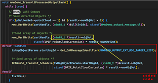
2. Add CAN transmit code in "void mmwDemo_TransmitProcessedOutputTask()" function, see follow picture
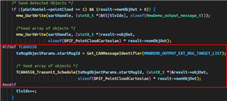
  

But there is a issue, the "Get_CANMessageIdentifier" function don't have "MMWDEMO_OUTPUT_EXT_MSG_TARGET_LIST" type, it will be judged as "CAN_MESSAGE_MMWDEMO_MAX"

Could you give me some advices to achieve the target list data transmission through CAN?

B.R.

  • Hi Li,

    To confirm, are you able to get the target list data transmitted, but getting the incorrect message ID? 

    If so, MMWDEMO_OUTPUT_EXT_MSG_TARGET_LIST can be added as an ID with minor modifications:

    1. In the mmwDemo_can_message_type enum, add CAN_MESSAGE_MMWDEMO_OUTPUT_EXT_MSG_TARGET_LIST as a high-priority ID.

    typedef enum mmwDemo_can_message_type_e
    {
        /*! @brief   List of detected points */
    -    CAN_MESSAGE_MMWDEMO_DETECTED_POINTS = 0xD1,
    +   CAN_MESSAGE_MMWDEMO_OUTPUT_EXT_MSG_TARGET_LIST = 0xD1,   
    
        /*! @brief   List of detected points */
        CAN_MESSAGE_MMWDEMO_DETECTED_POINTS,
    
        /*! @brief   List of detected points */
        CAN_MESSAGE_MMWDEMO_EXT_DETECTED_POINTS,
    
        /*! @brief   Range profile */
        CAN_MESSAGE_MMWDEMO_RANGE_PROFILE,
    
        /*! @brief   Noise floor profile */
        CAN_MESSAGE_MMWDEMO_NOISE_PROFILE,
    
        /*! @brief   Samples to calculate static azimuth  heatmap */
        CAN_MESSAGE_MMWDEMO_AZIMUT_STATIC_HEAT_MAP,
    
        /*! @brief   Range/Doppler detection matrix */
        CAN_MESSAGE_MMWDEMO_RANGE_DOPPLER_HEAT_MAP,
    
        /*! @brief   Stats information */
        CAN_MESSAGE_MMWDEMO_STATS,
    
        /*! @brief   List of detected points */
        CAN_MESSAGE_MMWDEMO_DETECTED_POINTS_SIDE_INFO
    
    } mmwDemo_can_message_type;

    1. In Get_CANMessageIdentifier(), add another conditional for MMWDEMO_OUTPUT_EXT_MSG_TARGET_LIST.

    mmwDemo_can_message_type Get_CANMessageIdentifier(MmwDemo_output_message_type type)
    {
        mmwDemo_can_message_type can_msgId;
    
    +   if(type == MMWDEMO_OUTPUT_EXT_MSG_TARGET_LIST) 
    +   {
    +       can_msgId = (mmwDemo_can_message_type)CAN_MESSAGE_MMWDEMO_OUTPUT_EXT_MSG_TARGET_LIST
    +   {
    *   else if(type == MMWDEMO_OUTPUT_MSG_DETECTED_POINTS)
        {
            can_msgId = (mmwDemo_can_message_type)CAN_MESSAGE_MMWDEMO_DETECTED_POINTS;
        }
        else if(type == MMWDEMO_OUTPUT_EXT_MSG_DETECTED_POINTS)
        {
            can_msgId = (mmwDemo_can_message_type)CAN_MESSAGE_MMWDEMO_EXT_DETECTED_POINTS;
        }

    In general, CAN IDs are intended to be customized for end application. As long as message priority and filters are kept in consideration, you can customize them to be whatever is needed.

    Thank you,

    Jin

  • Hi Jin,

    First, I have added below codes to get the target list data from UART for CAN data transmission, is this right?

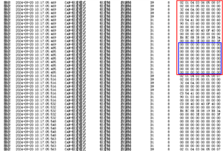
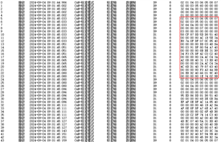
    Second, according to your suggestion, I added related code for MMWDEMO_OUTPUT_EXT_MSG_TARGET_LIST. Then, I test the CAN data transmission, we can see the data I receive from 1432, there are many 0 in the end of one frame data, I don't know if it is right?

    Thank you & B.R.

    Daowei

  • Hi Daowei,

    First, I have added below codes to get the target list data from UART for CAN data transmission, is this right?

    Yes, looks okay to me.

    Second, according to your suggestion, I added related code for MMWDEMO_OUTPUT_EXT_MSG_TARGET_LIST. Then, I test the CAN data transmission, we can see the data I receive from 1432, there are many 0 in the end of one frame data, I don't know if it is right?

    Seems like there is an empty message with 64 byte DLC being sent after the actual message. Could you share the values of uint8_t * result->objOut and sizeof(DPIF_PointCloudCartesian * result->numObjOut? You can view them in the Variables tab when running on CCS. 

  • Hi Jin,

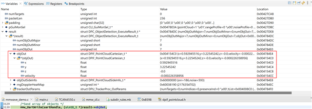
    Below are values of uint8_t * result->objOut

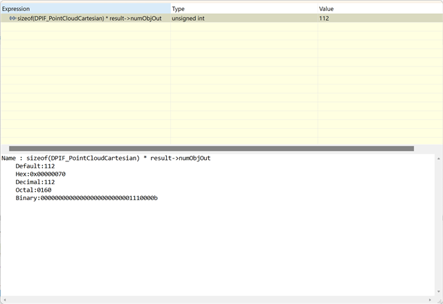
    Below is sizeof(DPIF_PointCloudCartesian * result->numObjOut

    FYI.

    Thank you & B.R.

    Daowei

  • Hi Daowei,

    Thanks for providing the screenshots. 

    The length of the CAN-FD transmit is correct. Given length=112, TCAN4550 will transmit a message of 128 (2*64 bytes). 

    However, mmw_UartWrite() is sending (uint8_t*)result->objOut, where as the TCAN4550_Transmit_Schedule is sending (uint8_t*)&results->objOut in the screenshot.

    This may be why the address of *(objOut) (=0x004154C0) (followed by the same sequence of random data) is being transmitted each time, rather than the object data itself. 

    Thank you,

    Jin

  • Hi Jin,

    According to your suggestion, I delete the & in front of results->objOut, and then the CAN message like this, please see below picture

    I think it is normal now, right?

    By the way, we still don't know how to decode the CAN message (the version is awrl1432_adas_bsd_demo_v2.2), could you give me some help?

    Thank you & B.R.

    Daowei

  • Hi Daowei,

    Yes, the data looks normal now.

    By the way, we still don't know how to decode the CAN message (the version is awrl1432_adas_bsd_demo_v2.2), could you give me some help?

    Because we are sending the same data over CAN-FD as over UART, the UART and OUTPUT to the HOST can be used as reference for the TLV structure:

    typedef struct DPIF_PointCloudCartesian_t
    {
        float x; /* x - coordinate in meters. */
        float y; /* y - coordinate in meters. */
        float z; /* z - coordinate in meters. */
        float velocity; /* radial velocity away from sensor in m/s */
    } DPIF_PointCloudCartesian;

    Therefore each point cloud structure is 16 bytes.

    If the question is in regards to interpreting the message from CAN bus, a CAN transceiver or tester (e.g. PCAN-USB) would be needed to receive the message.

    Thank you,

    Jin