This thread has been locked.

If you have a related question, please click the "Ask a related question" button in the top right corner. The newly created question will be automatically linked to this question.

TMCS1133-Q1: Parallel operation to reach higher currents

Part Number: TMCS1133-Q1
Other Parts Discussed in Thread: TMCS1133

Tool/software:

We are considering TMCS1133 for an application that requires measuring up to 84A continuous. Based on temperature derating and max amp ratings it looks like we cannot quite get there with this part. And unfortunately the Rth seems too high for effective heatsinking.

How feasible is it to put two of these parts in parallel to split the current between them? Even if the current splits unevenly, it seems we could sum the outputs from both devices to measure total current.

Are there any other issues we could run into with two TMCS1133 in parallel?

  • Hello Steven, 

    Thank you for your post. 

    This is a very interesting question. Let me look into the best options and get back to you on Monday (9/23).

    Thank you for your patience, 

    Joe

  • Hello Steven, 

    This is possible to do using two TMCS1133's.

    The most important thing is to make sure that each TMCS1133 is busbars are length matched and using the same material.

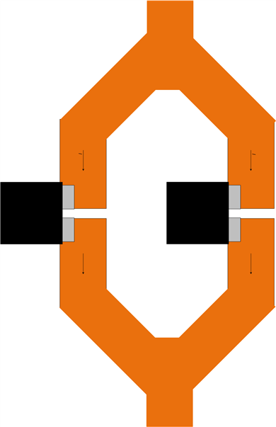
    Here are a couple of diagrams where I am trying to depict how I would suggest splitting your bus bar:

    1. The benefit of this first configuration is that the polarity of both devices is the same. Layout may be trickier for the LV signal routing. 
    2. This next option will need to have the polarity of the TMCS on the right corrected downstream. Layout may be more convenient. 

    Both of these configurations ensure that the CMFR of the device can remove the error from the other TMCS1133's busbar. 

    I hope this makes sense. 

    Thank you for your patience,

    Joe

  • Hi Joe,

    Thanks for your reply. These options look very similar to what we worked up.

    We actually prefer the 2nd layout since it allows us to use both Vout pins as a pseudo-differential voltage signal since one goes positive and the other negative due to the polarity flip. Also there's less parasitic capacitance on each isolated side side since the traces can escape out without crossing the power planes.