This thread has been locked.

If you have a related question, please click the "Ask a related question" button in the top right corner. The newly created question will be automatically linked to this question.

AWR6843ISK: Inquiry on Adjusting and Monitoring Transmitter Power in AWR6843/AWR1843/AWR1642

Part Number: AWR6843ISK
Other Parts Discussed in Thread: AWR6843, AWR1642, AWR1843

Tool/software:

Dear e2e Team,

I hope this message finds you well.

I would like to inquire about the process of adjusting the power or gain of the transmitters (Tx antennas) in the AWR6843, AWR1843, and AWR1642 devices. Additionally, could you please provide guidance on how the transmitted power can be monitored for validation purposes?

Your assistance on this matter would be greatly appreciated.

Thank you for your time and support.

  • Hi, there:

    If you are running any TI demo, you should be able to change the TX power by change the profileCfg CLI.  The detailed field <txOutPower> can be found in the SDK doxygen documentation below.  (you may need to change the SDK version name to match your download version)

    file:///C:/ti/mmwave_sdk_03_06_00_00-LTS/packages/ti/control/mmwavelink/docs/doxygen/html/structrl_profile_cfg__t.html

    For verification, you can run OOB demo in the clean environment with a corner reflector.  Without change the RX gain, target position, and just adjust the tx power level as above, you should be able to see the peak signal level adjust accordingly. 

    Best,

    Zigang

  • Hi, 

    Thank you for the useful answer. I changed txOutPower according to your advised doxigen link and explanation in the below link:

    https://e2e.ti.com/support/sensors-group/sensors/f/sensors-forum/945799/iwr6843-how-to-change-the-tx-power-using-the-configuration-file

    Next, I tested the AWR6843 sensor with original configuration and decreasing txOutPower to 06 dB from original in config file as below:

    [original] profileCfg 0 60 7 6 48 0 0 83 1 512 12500 0 0 176

    [modified] profileCfg 0 60 7 6 48 394758 0 83 1 512 12500 0 0 176

    However, surprisingly, the output with both configurations are similar. Should I need to modify some lines in the firmware. If yes, would you guide me which part of the firmware code should be change? I apply AWR6843, demo version in mmwave_sdk_03_06_02_00-LTS.

    Thank you in advance for your help and advice.

    Best Regards

  • Hi, Ramin:

    That is surprising!  Were you using a corner reflector?  Can you send me the OOB demo visualizer output for both configurations?  for example, the range profile figure.  

    Best,

    Zigang

  • Hello Zigang, 

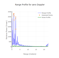
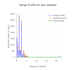
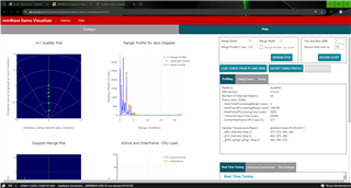
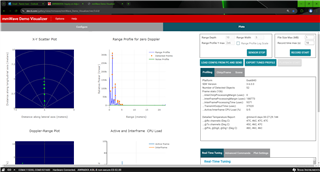
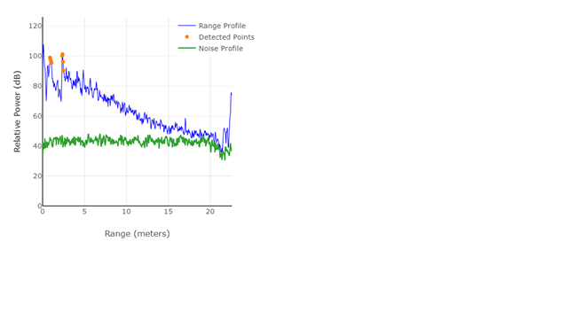
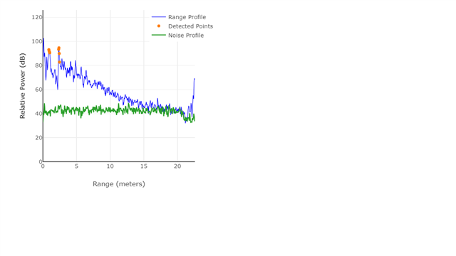
    I apologize for forgetting to attach the visualizer output. The figure on the left shows the Range Profile with the original configuration, while the figure on the right corresponds to the modified configuration where the Tx power was reduced by 6 dB. As expected, the amplitude decreases by a factor of four.

    Please note that the first peak represents the reflector, while the second, larger peak is from the ground reflection.

    Additionally, I conducted the experiment with different Tx power levels, but the outputs remained consistent across all variations.


  • HI, there:

    That is really strange.  Can you double check the configuration that loaded in visualizer is the one you made the change?  

    Best,

    Zigang

  • Hello, 

    I just double checked the configuration attached bellow. The Tx power is only option I have changed in original config file. I upload standard bin file of the demo version. It means nothing was changed in the setup except Tx power. 

    % Carrier frequency GHz 60
    % Ramp Slope MHz/us 166
    % Num ADC Samples 256
    % ADC Sampling Rate Msps 12.5
    % ADC Collection Time us 20.48
    % Extra ramp time required (start time) us 3
    % Chirp time (end time - start time) us 21
    % Chirp duration (end time) us 24
    % Sweep BW (useful) MHz 3399.68
    % Total BW MHz 3984
    % Max beat freq (80% of ADC sampling rate) MHz 10
    % Max distance (80%) m 9.04
    % Range resolution m 0.044
    % Range resolution (meter per 1D-FFT bin) m/bin 0.044
    %
    % Inter-chirp duration us 7
    % Number of chirp intervals in frame - 64
    % Number of TX (TDM MIMO) 2
    % Number of Tx elevation antennas 0
    % Number of RX channels - 4
    % Max umambiguous relative velocity kmph 72.58
    % mileph 45.36
    % Max extended relative velocity kmph 145.16
    % mileph 90.73
    % Frame time (total) ms 1.984
    % Frame time (active) ms 1.536
    % Range FFT size - 256
    % Doppler FFT size - 32
    % Radar data memory required KB 272
    % Velocity resolution m/s 1.26
    % Velocity resolution (m/s per 2D-FFT bin) m/s/bin 1.26
    % Velocity Maximum m/s 20.16
    % Extended Maximum Velocity m/s 40.32
    % Maximum sweep accorss range bins range bin 0.91
    %
    sensorStop
    flushCfg
    dfeDataOutputMode 1
    channelCfg 15 5 0
    adcCfg 2 1
    adcbufCfg -1 0 1 1 1
    lowPower 0 0
    profileCfg 0 60 7 6 48 394758 0 83 1 512 12500 0 0 176
    chirpCfg 0 0 0 0 0 0 0 1
    chirpCfg 1 1 0 0 0 0 0 4
    frameCfg 0 1 16 0 200 1 0
    guiMonitor -1 1 1 1 0 0 1
    cfarCfg -1 0 2 8 4 3 0 15.0 0
    cfarCfg -1 1 0 4 2 3 1 15.0 0
    multiObjBeamForming -1 1 0.5
    calibDcRangeSig -1 0 -5 8 256
    clutterRemoval -1 0
    compRangeBiasAndRxChanPhase 0.0 1 0 1 0 1 0 1 0 1 0 1 0 1 0 1 0 1 0 1 0 1 0 1 0
    measureRangeBiasAndRxChanPhase 0 1. 0.2
    aoaFovCfg -1 -90 90 -90 90
    cfarFovCfg -1 0 0.25 9.0
    cfarFovCfg -1 1 -20.16 20.16
    extendedMaxVelocity -1 0
    CQRxSatMonitor 0 3 4 63 0
    CQSigImgMonitor 0 127 4
    analogMonitor 0 0
    lvdsStreamCfg -1 0 0 0
    bpmCfg -1 0 0 0
    calibData 0 0 0
    sensorStart

  • Hi, there:

    I tried on my side, and see a change in range profile.

    Can you make sure you see the profile change in the console window after you load the updated configuration file?

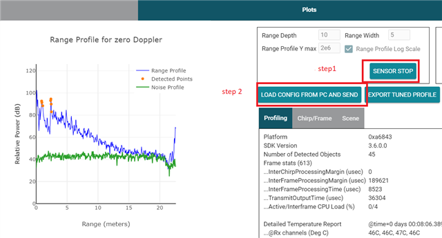
    Please use the button below to load the configuration file, and remember to stop the sensor first before loading.

    Best,

    Zigang

  • Hello Zigang, 

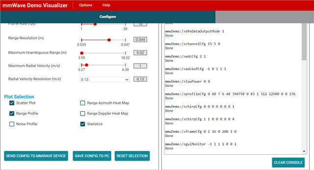
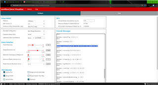
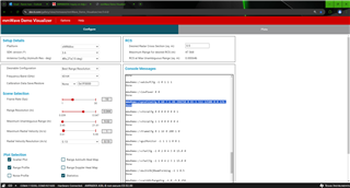
    Thank you for your help and attention. Attached are screenshots of the console and the corresponding Range Profile after loading the configuration with the two specified output powers. However, I still do not see any significant changes.

  • Which demo you are using? Mine was shown a range profile in dB (instead of linear) and the level change looks right to me. 

    Best,

    Zigang

  • Hello, 

    I am using mmwave_sdk_03_06_02_00-LTS. Fortunately, with the help of your comments, I was able to identify the issue. The problem was caused by the short distance between the reflector and the sensor. The reflected power was significantly higher than the sensor’s memory capacity, causing memory saturation. Even after reducing the power, the reflection remained strong enough to saturate the memory. I replaced the reflector with a smaller aluminum plate, which allowed me to observe differences in the output, although the results still do not seem accurate. I will ask this in another thread.

    Thank you very much for your guidance and for taking the time to assist me.