This thread has been locked.

If you have a related question, please click the "Ask a related question" button in the top right corner. The newly created question will be automatically linked to this question.

AWR1843BOOST: Beamforming for Reducing the HPBW

Part Number:  AWR1843BOOST

Tool/software:

Greetings Forum!

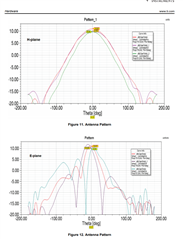
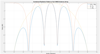
The azimuthal HPBW on the AWR1843BOOST is very wide and it does not align well with our application of wall detection at a distance. Is there a possibility to reduce the HPBW through beam forming. The attached picture is what I intend to achieve. This photo is taken from the documentation on MIMO Radar from Math works. Per the theory behind beamforming, I must enable both Tx antennae in the azimuth plane at the same time. How do I achieve that in the software?

Moreover, as I understand, the BPM-MIMO serves the purpose well as it offers simultaneous transmission from both Tx antennae and allows for fine angular resolution as well. However, if we are not interested in angular resolution at all and the aim is to just reduce the HPBW and receive the reflected signal with a single Rx antenna then how does the situation change.

Please guide

Best Regards

Maaz Ali Awan

  • Still waiting for 02 days now please.

    Best Regards

  • Hi Maaz,

    Thank you for your patience. Please find my responses below:

    1. You can find the right antenna pattern diagram from the AWR1843BOOST EVM user guide as below:
    2. You can also refer to the MRR Beam steering example available as part of the Radar Toolbox for more information on this topic with respect to achieving a narrower beam width.

    Please let me know if there are any further questions.

    Regards,

    Kaushik

  • Greetings Sir!

    No issues with waiting as long as we are guided in the right direction. Slight smile

    Thank you for the responses. 

    1. I am already aware of the radiation pattern from the user guide of the AWR1843BOOST.

    2. I am also aware of the MRR beam steering example but I need some clarity on the radiation pattern. Since the antenna are separated by 2λ, the radiation pattern will have multiple grating lobes instead of a single main lobe in the center. Check the "Tx Pattern" in the attached picture of my original post. 

    The documentation in MATLAB from where I took the picture suggests that the MIMO radar with the ability to create a virtual antenna array of 8 receive antennae with 2 Tx and 4 Rx physical antenna resolves this problem. As I understand, if I use 2 Tx-R 4x BPM-MIMO, I shall have a reduced HPBW and the issues of grating lobes will be resolved? 

    What if I want a 2 Tx- 1 Rx configuration where the aim of having 2 Tx is just to reduce the HPBW and the only 01 receiver chain to keep the computation latency to a bare minimum. Given the grating lobes issue, it might not be a possibility. 

    I need your guidance in this matter because I dont have a compact antenna testing range (CATR) to characterize radiation pattern at 77 GHz frequency. The MATLAB simulations is all I am relying upon.

    Please guide me through this challenge.

    Best Regards

    Maaz Ali Awan

  • In the meantime, I was able to perform a simulation in MATLAB and this is what I got. Compare this blue curve with the blue curve of the picture in the original post. Your comments on the simulation results are highly solicited.

    Best Regards

    Maaz Ali Awan

  • A response is highly appreciated please.

    Regards