This thread has been locked.

If you have a related question, please click the "Ask a related question" button in the top right corner. The newly created question will be automatically linked to this question.

MMWCAS-RF-EVM: Calibration / Chirp Configuration

Part Number: MMWCAS-RF-EVM
Other Parts Discussed in Thread: AWR2243, AWR2243BOOST, AWR1243

Tool/software:

Hello,

I am working with the MMWCAS RF / DSP Evaluation kit for cascade radar. I adjusted the configuration for a short range/high resolution setup resolution in MIMO mode (chirp slope, sample rate, ramp time, number of chirps per frame). Now I wanted to do a calibration using this short range configuration.

The setup has been made in an empty room ~5m wide / ~12m long with a corner reflector placed in the middle of the room at 5m distance from the RF board.

Standard MIMO Config Short Range MIMO Config
local hpfCornerFreq1 0 0 0: 175KHz, 1: 235KHz, 2: 350KHz, 3: 700KHz
local hpfCornerFreq2 0 0 0: 350KHz, 1: 700KHz, 2: 1.4MHz, 3: 2.8MHz
local nframes_master 10 10 Number of Frames for Master
local nframes_slave 10 10 Number of Frames for Slaves
local trigger_delay 0 0 us
local trig_list {1,2,2,2} {1,2,2,2} 1: Software trigger, 2: Hardware trigger    
local start_freq 76 76 GHz
local slope 19.53125 50.018 MHz/us
local idle_time 7 7 us
local adc_start_time 7 7 us
local adc_samples 256*2 256*2 Number of samples per chirp
local sample_freq 16000 6000 ksps
local ramp_end_time 249 98 us
local rx_gain 30 30 dB
local Inter_Frame_Interval 200 200 ms
local nchirp_loops 64 128 Number of chirps per frame

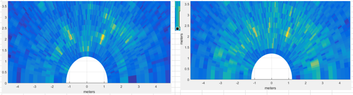
As the results of the calibration using the adjusted configuration seemed do be somehow off I repeated the measurements and calibration script few minutes later without adjusting anything besides the configuration file. The target reflection is marked with"1" (actual distance: 501cm), the reflection of the wall behind is marked with "2" (actual distance not measured exactly).

Results Short Range Configuration

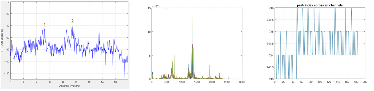
The sampled chirp bandwidth results in a range resolution of ~3.5cm. Analyzing the samples in PostProc the peak indicates a distance of ~521cm, hence off by 21cm / 5 bins of the range resolution. Running the antenna calibration matlab script hence results in a estimated target range of 5.2013m. The reflection of the wall results in a distance of 941cm.

Results Standard MIMO Configuration

The sampled chirp bandwidth results in a range resolution of ~60cm. Analyzing the samples in PostProc the peak indicates a distance of ~480cm, hence off by 20cm, but falling within the range of the range resolution. Running the antenna calibration matlab script results in a estimated target range of 5.0344m.The reflection of the wall results in a distance of 939cm.

Questions

  1. Is the matlab calibration script intended to be used with a specific configuration of the chirp profile?
  2. How can the deviation of the short range configuration be explained?
  3. Is there a way to calibrate the RF board by entering the exact distance of the target (the entered value at the matlab script only seems to set a point, where a local maximum is to be expected) and hence scaling the result  up or down?
  4. There are limits in MMWAVE Studio regarding the chirp parameters. Is there a document besides "Programming Chirp Parameters in TI Radar Device" that handles how to configure the chirp parameters, especially for the MMWCAS setup? Something like a "best practice" document, stating e.g. "keep the sample rate as high as possible".
  5. mmWaveSensingEstimator:
    1. The MMWCAS cannot be chosen for the AWR2243 or AWR1243. Can the AWR2243BOOST EVM board values be used for the MMWCAS EVM as well?
    2. The No. of samples per chirp in the MMWCAS is limited to 512, in the mmWaveSensingEstimator the sample rate exceeds that number at range resolutions < ~7cm. Is the maximum number of samples per chirp somehow limiting the usable bandwidth of the MMWCAS EVM?

Thanks and kind regards

Felix

  • Hi Felix,

    Is the matlab calibration script intended to be used with a specific configuration of the chirp profile?

    I hope that you are referring to the MATLAB scripts from C:\ti\mmwave_studio_03_00_00_14\mmWaveStudio\MatlabExamples. If that is the case, you should be able to use the same scripts with custom configuration.

    How can the deviation of the short range configuration be explained?

    Both the images attached are same. Can you update the screenshot for short range?

    Is there a way to calibrate the RF board by entering the exact distance of the target (the entered value at the matlab script only seems to set a point, where a local maximum is to be expected) and hence scaling the result  up or down?

    Refer to Imaging Radar Using Cascaded mmWave Sensor Reference Design (Rev. A) (ti.com). This document provides details on how calibration is performed. You can also use the lua scripts located at C:\ti\mmwave_studio_03_00_00_14\mmWaveStudio\Scripts\Cascade to configure the cascade EVM.

    There are limits in MMWAVE Studio regarding the chirp parameters. Is there a document besides "Programming Chirp Parameters in TI Radar Device" that handles how to configure the chirp parameters, especially for the MMWCAS setup? Something like a "best practice" document, stating e.g. "keep the sample rate as high as possible".

    Here are few documents for your reference,

    As mentioned in the reply to your third question, we provide sample lua scripts as an example.

    Sensing estimator doesn't support configuring cascade EVM.

    Regards,

    Samhitha

  • Hi Samhitha,

    thanks for the reply.

    I hope that you are referring to the MATLAB scripts from C:\ti\mmwave_studio_03_00_00_14\mmWaveStudio\MatlabExamples. If that is the case, you should be able to use the same scripts with custom configuration.

    yes, I am. OK!

    I updated the screenshots, seems the website can't display 2 different graphics with identical names.

    Refer to Imaging Radar Using Cascaded mmWave Sensor Reference Design (Rev. A) (ti.com). This document provides details on how calibration is performed. You can also use the lua scripts located at C:\ti\mmwave_studio_03_00_00_14\mmWaveStudio\Scripts\Cascade to configure the cascade EVM.

    Thanks for the document, thats where I got the setup from. unfotunately I don't have the chance to go into a absorber chamber and only can do it in an empty room, as discribed in my post. Is that an issue or is a more or less reflection free room needed? To my understanding only reflections near the 5m target (+-1m according to the manual) should be free of reflecting objects.

    Here are few documents for your reference,

    I'll check these documents, but I think I know them by now.

    As mentioned in the reply to your third question, we provide sample lua scripts as an example.

    Thats the standard scripts I've been using and adjusted for a different chirp profile.

    Sensing estimator doesn't support configuring cascade EVM.

    I know, but can you tell me if I can use the AWR2243BOOST board, which uses the identical chipset as my MMWCAS_RF board as reference for the chirp profile as it is the identical chipset?

    Please check my updated screenshot and reach out to me, I am not sure if the calibration data can be used like that.

    Best regards

    Felix

  • Hi Felix,

    I will check your reply and get back to you by Tuesday.

    Regards,

    Samhitha

  • Hi,

    ok, thanks! Here some data for comparison of the short range and mid range configuration. Each row is the same capture data. The left hand side of each row is the matlab post processing using the calibration matrix that has been generated with configuration data of my own, short range configuration, the right hand side is the same data, but post processing done with a calibration matrix generated with the configuration of the standard MIMO (midrange) script provided by TI.

    Mid range MIMO capture data (standard TI, same left and right)

    Short range MIMO capture data (own, same left and right)

    So to me it seem the calibration with the standard MIMO parameters is not as accurate, it seems to have problems when being used with higher bandwidth configurations.

    Best regards

    Felix

  • Hi Felix,

    The left hand side of each row is the matlab post processing using the calibration matrix that has been generated with configuration data of my own, short range configuration, the right hand side is the same data, but post processing done with a calibration matrix generated with the configuration of the standard MIMO (midrange) script provided by TI.

    If you are using a different configuration, you need to generate the calibration matrix. You cannot use calibration matrix generated with the mid-range configuration to calibrate the data captured with short range configuration.

    I know, but can you tell me if I can use the AWR2243BOOST board, which uses the identical chipset as my MMWCAS_RF board as reference for the chirp profile as it is the identical chipset?

    Sensing estimator is just for reference, it might not provide accurate results.

    Regards,

    Samhitha

  • Hello Samhitha,

    thanks for your reply. As I understood the mmw_cascade_user_guide the calibration procedure is a 1-time procedure and independent from the cascade configuration:

    8.3.2.2, p. 31: This step is required only once for each Cascade RF-EVM. Once you have the calibration matrix, it can be used for any future captures with the same EVM setup.

    To my understanding of the PDF regarding the calibration procedure the calibration matrix is to compensate manufacturing caused, physical mismatches between individual boards (e.g. position misalignment of antenna, phase difference due to route delay mismatch etc) and therefore should be independent from the chirp profile.

    Is the following ok:

    unfotunately I don't have the chance to go into a absorber chamber and only can do it in an empty room, as discribed in my post. Is that an issue or is a more or less reflection free room needed? To my understanding only reflections near the 5m target (+-1m according to the manual) should be free of reflecting objects.

    And how can the deviation of several 10 cm in short range configuration be explained:

    Analyzing the samples in PostProc the peak indicates a distance of ~521cm, hence off by 21cm / 5 bins of the range resolution.
    How can the deviation of the short range configuration be explained?

    Regards

    Felix

  • Hi Felix,

    If you are using a different configuration, you need to generate the calibration matrix. You cannot use calibration matrix generated with the mid-range configuration to calibrate the data captured with short range configuration.

    Seems like I have misunderstood your question. By the above statement, I meant that you need to use short range configuration to perform the calibration when you have captured the ADC data with short range configuration. Once you have the matrix, you should be able to use the same calibrated data for various configurations.

    And how can the deviation of several 10 cm in short range configuration be explained:

    In general, it's expected to see a deviation of 5-10 cm. I will check about this internally and let you know what can cause 20cm deviation. 

    Regards,

    Samhitha

  • Hi Felix,

    After checking the plots (1D FFT), I have observed that there is 2cm difference for the wall that is detected using both the configurations. So, 20cm difference that you have mentioned is not uniform for all the detected objects. Can you perform few tests by moving the target to different locations and see if the results are similar?

    Can you confirm if you are using a strong reflector as your target? Also what are the dimensions of the target?

    Regards,

    Samhitha