This thread has been locked.

If you have a related question, please click the "Ask a related question" button in the top right corner. The newly created question will be automatically linked to this question.

TMAG3001: Daisy-Chain for address assignment on startup

Part Number: TMAG3001

Tool/software:

Hello TI,

in a new project, I have to replace a level sensor design that uses hall switches. The goal is to get a continuous fluid level value..

Depending on the length of the device, I will need up to 40 sensors, each requiring an unique I2C address. I could imagine to set up a chain like this:

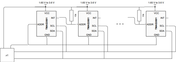
40 pcs. of Tmag3001 are all connected to VCC and GND. The address pin of each device has a pull-up to VCC and is connected to the INT pin of the preceding TMAG3001. Only the address pin of the first TMAG3001 is connected to ground. This way, I could imagine to achieve a different address of the first sensor on power up, which will allow to address it explicitly and set a new unique address using its registers. Furthermore, I would be able to configure the first sensor to pull its INT-pin low to change the address of the second sensor. Thereby giving it a unique address for being able to repeat the seps I mentioned for the first sensor.

Now the main question: When does the TMAG3001 sample the address pin? Is it possible to change the address (using the address pin) during operation? Is there another recommended way to solve this issue?

Best regards, 

Markus

  • Hi Markus,

    Thank you for posting to the Sensors forum!

    Would it be possible to get a diagram of the way you plan on daisy chaining the devices together to help me visualize what you are trying to do?

    When does the TMAG3001 sample the address pin?

    The TMAG3001 samples the address pin at startup. 

    Is it possible to change the address (using the address pin) during operation

    Yes.

    Best,

    ~Alicia

  • Hello Alicia,

    here's a quick draft of what I'm thinking about for the schematic:

    In this topology, the sensors are initialized from left to right. During initialization, each sensor gets an unique address by witing its I2C_Address register. The INT-pin of the last initialized sensor is used to pull the ADDR-pin of the next sensor low, giving him address = 0x34. All other not initialized sensors are at address 0x35.This gives me the possibility to step through the row of sensors during initialization by always setting a unique address for the sensor with address 0x34.

    I think your answers are in conflict with each other. If the device is only sampling the ADDR-pin at startup, it cannot be changed during operation. Can you please clarify? I hope the sensor is sampling its address on receiving an I2C-Frame...

    Best regards,
    Markus

  • Hi Markus,

    Apologies for the conflicting answers previously, the ADDR pin is not only sampled at startup as it is continuously sampled gets sampled while in standby/continuous mode. This way it is possible to change the address using the ADDR pin during operation so long at you are in standby or continuous mode as the ADDR pin is not sampled in sleep/W&S mode.

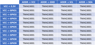
    Regarding how to go about giving a unique address to each of the 40 potential devices, I would recommend something similar to the table below:

    The way this method would work is that you would have the VCC of the first 4 devices tied directly to 3.3V. The VCC of the next set of 4 devices can then be powered from one of the GPIO pins of the MCU. Continue connecting the VCC of the TMAG3001s in groups of 4 to other GPIOs until all are connected.

    This way you start with 4 devices powered on (with all others powered off) with each of their ADDR pins being tied to either VCC, GND, SCL, or SDA so that all 4 devices have a different default I2C address. From here, change all of their I2C addresses via the I2C_Address register. Next, power on the next set of 4 devices and change their respective I2C addresses. Continue until all are powered on and have a unique I2C address.

    Note that the GPIO pins need to be able to power each of these devices. If there are limitations to how much current can be drawn from them, you can also use load switches that are triggered based on the GPIO pins to power them.

    Best,

    ~Alicia