This thread has been locked.

If you have a related question, please click the "Ask a related question" button in the top right corner. The newly created question will be automatically linked to this question.

LDC1001: Detecting large metal objects that causes sensor overload

Part Number: LDC1001

Tool/software:

Hello,
We use the LCD1001 sensor to detect the presence of metal objects on our product.

We are able to detect several types of objects of different sizes, but larger objects cause the sensor to overload.
We can't currently change our HW design to properly detect these objects (to get an RP between RPmin and RPmax).
We'd like to know how to detect that the sensor is overloaded so that we can send the alert back to our product.

We've thought of using the STATUS register (0x20) and catching the oscillator timeout events, but is this a foolproof method?
We saw in the datasheet that one of the causes of this error (oscillator timeout) is an Rp lower than RPmin. But we don't know if this is a reliable way of concluding that the sensor is overloaded. 
Is this the only way to conclude that the sensor is overloaded by a large metal object?
If that's not enough, how can we be sure that a large metal object is causing the sensor to overload?
Is there more than one piece of data that can be cross-checked to obtain a reliable conlusion? 

Best regards. 

  • Hi Moustapha,

    I think monitoring the OSC status is a good method to detect when the sensor is overloaded.  I think it may also be good to check the inductance/frequency measurement for additional information confirming a large object.  You will need to characterize this, but I would expect that you see a larger inductance shift as well when  large metal object is used.  

  • Hi Moustapha,

    I think monitoring the OSC status is a good method to detect when the sensor is overloaded.  It may also be good to check the inductance/frequency measurement for additional information confirming a large object.  You will need to characterize this with expected large, small, and medium objects, but I would expect that you see a larger inductance shift as well when  large metal object is used.  See section 7.3.3 of the datasheet.

    https://www.ti.com/lit/ds/symlink/ldc1001.pdf 

  • Hello Eddie, thank you for your reply,

    I'm going to study the variation of the inductance with the distance and the size of the metal obejct.

    What about proximity data?
    What is its expected value when the sensor is overloaded?

    From what I've noticed, the value is similar to when no tool is in front of the sensor. Is this the expected behavior?


    Best regards.

  • I ask this question because according to the datasheet it says:

    ""When the resonance impedance of the sensor, RP, drops below the programmed Rp_MIN, the RP output of the
    LDC will clip at the full scale output. An example occurrence of this situation is when a target comes too close to
    the coil.""

    So I expected the Proximity data value to be very large and equal to its maximum.

    Maybe I've misunderstood this part about clipping data.

    Can you clarify this for us? 


    Best regards.

  • Hi Moustapha,

    Eddie is currently out of office today. He will be back next week and should be able to get back to you then.

    Best,

    ~Alicia

  • Hello Eddie,

    I couldn't measure the inductance variation because we don't have external clock applied on TBCLK pin on our products.
    So we are unable to measure inductance via Frequency Counter Data registers.

    If we make sure that Min Sensor Frequency is set correctly, can we assume that the only possibility of having a sensor oscillation timeout is the case where
    R < Rpmin, which means that we have a larger object than anticipated when setting Rpmin?

    Can we also use Proximity data to reach a more reliable conclusion?

  • Hello,

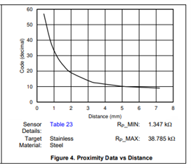
    Yes, you should be able to also monitor the proximity data as well to determine if a target is overloading the sensor.  You should see a curve similar to figure 4 below.  

    Another scenario where the sensor oscillation timeout could occur is if there is a change in the coil affecting the resonant frequency.  For example, if multiple turns of the coil were shorted together or coil is broken(open circuit).