This thread has been locked.

If you have a related question, please click the "Ask a related question" button in the top right corner. The newly created question will be automatically linked to this question.

TMAG6180-Q1: Mounting instructions

Part Number: TMAG6180-Q1
Other Parts Discussed in Thread: TMAG6180

Tool/software:

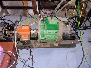
I'm developing a drive circuit for switched reluctance machine. The machine is 3500W. I have following doubts on using TMAG6180-Q1 as rotor angle sensor.

1. Can i use this sensor for a big machine like this?

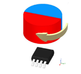
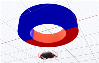
2. can you provide mounting instructions to mount magnet the shaft and placing the IC on the same axis of magnet. If  
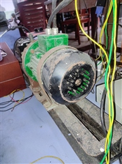
you have any pictures or application notes regarding mounting that would be of great help.

3. what type of magnet should i use on the center of the shaft?

  • Hello Abhinav,

    Thanks for posting to the sensors forum! The TMAG6180-Q1 could definitely be used with a reluctance motor as you have shown here.

    Typically for the TMAG6180-Q1 it is recommended that the sensor is mounted on axis with the magnet and typically with a diametric cylinder magnet (see image below).

    We do have a document that covers some of the mounting information you are inquiring about but mostly covers information regarding sensor calibration, that document can be read following this link: https://www.ti.com/lit/an/slya085/slya085.pdf

    For more help on how the sensor should be mounted and perhaps what you would expect from different magnet types I would suggest checking out our simulation tool TIMSS: https://webench.ti.com/timss/

    This tool is free to use and would allows you to input different types of magnets, play with magnet magnets position, strength, all while providing device emulation so that you know what to expect from the sensor.

    Please let me know if there are any other questions I can help out with or if any help is needed getting you started on a simulation.

    Best,

    Isaac

  • Abhinav,

    The TMAG6180 is intended for motor position sensing, and should be able to track a motor of any size.  As you point out, a particular concern for this application is mounting the sensor to the motor shaft.  One end of your shaft is clearly occupied through a coupler that connects to the equipment being driven.  We would need to be able to access the opposite end of the motor shaft and fix a diametric magnet onto this end.  I cannot tell in your first picture whether or not you have clear access to this, or if perhaps we are seeing some other part of the casing

    To mount to back side of the motor, you could use a solid cylinder magnet inserted into a fixture with a cutout, or you may possibly also use a ring magnet with an ID that matches the shaft diameter.  The sensor should then be placed with the  center of the die aligned to the center of the rotation axis:

    The strength of the magnet just needs to be such that the sensor is exposed to >20mT throughout the full rotation of the motor, but any magnet material will be sufficient if this requirement is met.  SmCo magnets have very low temperature dependance compared to other magnet materials, but are often more expensive.  NdFeB are common and produce strong magnetic fields, and Ferrite/Ceramic magnets are often the most economical.

    Thanks,

    Scott