This thread has been locked.

If you have a related question, please click the "Ask a related question" button in the top right corner. The newly created question will be automatically linked to this question.

AWRL6432: Question on rxgain

Part Number: AWRL6432


Tool/software:

Hi,

In mmwave_dfp_interface_control_document.pdf, customer found the value range for rxgain is 30dB to 40dB. Is there any problem to set rxgain lower than 30dB? I think it will cause lower signal gain/SNR. Would you pls comment?

Thanks,

Chris

  • Hi Chris,

    For 6432, the valid range for Rx gain is [30,40]. If we use Rx gain lesser than 30dB then the SNR gets impacted, and we will not be able to achieve same Rx gain at the lower temperatures because of the flatness of Rx gain across temperatures.

    Thanks.

  • Voona,

    Customer found if they set the RX gain to 20dB, there will be jitter or discontinuous issue on ADC data sometimes. Why this will happen?

    Thanks,

    Chris  

  • Hi Chris,

    It is not recommended to use Rx gain outside of the valid range [30,40]. It could be possible that you see similar issues when you use less Rx gain which is out of range. Could you tell what is the Tx power backoff being used by customer? Is it 0dB backoff?  

    Thanks,
    Deexith.

  • Hi Deexith,

    Thank you for your patient reply!Tx power backoff is 0dB. We thought that reducing the TX power might reduce the SNR.The saturated ADC waveform is shown in the attached figure, could you tell me which module is saturated at the receiver? 


    Thanks, 

    Laijun

  • Hi Laijun,

    • Valid range for the Rx gain is 30-40dB. It is recommended to use the Tx backoff. And yes, Tx backoff will decrease the SNR.
    • The above plots show that ADC module is saturated. You can increase the attenuation of the low frequency signal by increasing the HPF setting or reducing the slope.

    Thanks,
    Deexith.

  • Hi Deexith,

    Thank you for your reply!We set HPF=2 and Rxgain=30. The saturation problem disappears, but sometimes the ADC waveform produces step jumps, which increases the noise significantly after 2Dfft. Pls what is the reason for this and how do I fix this next. Thank you!ADC waveform_Jump

    Thanks,
    Laijun.

  • Hi Laijun,

    The shared ADC data plot shows that all the chirps are overlapping. Hence, we do not expect any noise after 2DFFT based on this plot. Can you please tell what are your RDIF configurations?

    Also, can you please share us the .mat file of the ADC data to understand about the noise you are mentioning? Are you using the Corner Reflector as target object?

    Thanks,
    Deexith.

  • Hi Deexith,

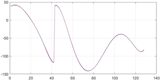
    I'm sorry I made a mistake, this step really didn't increase the 2Dfft noise, but I think there will be a change in the distance dimension at zero velocity.  It's uncertain if this could cause other problems.

    The radar is mounted on the door of the car and the data is collected when electromagnetic waves are emitted into the car. The ADC .xlsx data  for the TX0RX0 is available in the  attachment(chirp:128,dot:128). Correspondence this figure:

    Also,I consulted with our software engineers,RDIF configure is same as the program of the AWRL6432 demo board.

    Thanks.

    Laijun.

    AWRL6432_TX0RX0_ADC.xlsx

  • Hi Laijun,

    Can you also let us know how far is the detected object from the ground truth at zero doppler? And was there no person sitting in the car while capturing the ADC data?

    Thanks.