


Tool/software:
Hi.
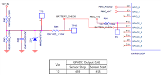
We are monitoring the input voltage through channel 2 of the GPADC on the AWR1843AOP, as shown in the diagram below.
However, as indicated in the table within the same diagram, there is a difference of about 4 bits in the ADC readings between the sensor stop state and the sensor start state.
To address this issue, we modified the circuit.
As shown in the diagram below, we removed the 10nF capacitor (C86) or replaced it with a capacitor of 120pF or lower, which resolved the issue.
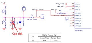
Our question is: Why does the GPADC value differ between the sensor start and sensor stop states when the capacitor (C86) value is 10nF?
