Other Parts Discussed in Thread: HDC2080
Tool/software:
I am trying to connect with BP-BASSENSORSMKII development board with F28379D launchpad.
The example that has been made by Mathwork team is supposed to work. I did all the required steps, but still getting zero results.
Then I used I2C scanner example from Arduino, and it detects only 0x40 address (HDC2080) from the BP-BASSENSORSMKII development board. I gave the I2C address (0x69) for IMU according to datasheet but no result. Is (BOOSTXL-SENSORS) different than BP-BASSENSORSMKII?
Connection:
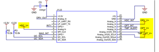
BP-BASSENSORSMKII plug-in module to the F28379D LaunchPad.
Connected GPIO104 and GPIO105 pins on the F28379D Launchpad to the J1.10 (SDA) and J1.9 (SCL) pins respectively on the BP-BASSENSORSMKII,
VCC = 3.3V
GND
My questions
Do you have any working example that can work with BP-BASSENSORSMKII sensors and F28379D?
Why the sensor module is only showing 0x40 address (HDC2080) instead of all other sensors I2C address?