Because of the Thanksgiving holiday in the U.S., TI E2E™ design support forum responses may be delayed from November 25 through December 2. Thank you for your patience.

LDC5072-Q1: Sensor Designer Linear II issue

Part Number: LDC5072-Q1

Tool/software:

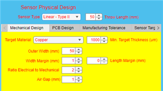
Are there any tricks to get the Sensor Designer to generate with Sensor Type "Linear - Type II" ?  Everything I try just gives me some type of error beep, and the Design button stays yellow.

Alternately, a 250mm+ reference design could be helpful.

  • Hello Erik,

    Currently, the linear sensor types are not supported in the tool, but I can help to generate the coil for you.  Can you please provide the parameters shown below?  

  • This is what I was trying to build, although I am unclear on the results.

    Ideally I need 250mm detection length, so depending how the tool builds, it needs to add the sensor length as well I believe.  I'm also not clear if 25mm is wide enough, but my design is flexible enough I can adjust the target size and overall width.

  • Thanks Erik.  I will work on a coil design and provide it by end of the week.

  • Another vendor advised me that 100mm+ linear sensors are difficult, is this an inherent limitation here?  My max dims on this would be, Coil PCB of 25.4mm x 381mm, with max target size around 23mm x 127mm

  • Erik,

    It is not an inherent limitation of the technology.  I think they may have been inferring that larger coils require higher drive strength of the excitation coil that some devices may not provide.  We have not tested any with 250mm throw length, but we do have a design we are planning to test with 180mm length.  We have not had the PCB's manufactured for this design yet, but we are planning to in the next few weeks.  

    I have attached gerbers for 250mm throw length.  Let me know if there are other questions.SensorGerber1.zip

  • Thank you.  A couple questions about the design, the sin/cos coils are only around 2.5mm tall, that seems real shallow.  Is there a particular reason that 1mm traces were chosen rather some much thinner traces and a large sin/cos width? I'd be curious what the real world resolution would be for this coil.

  • Green would be sensor coil, and yellow the target.  In this case, block and tube are aluminum, so I'm not sure how this would work spacing wise, or if I'd have to move the sensor away from the tubes and extend the yellow target so I don't have aluminum interfering with the coil.

  • Erik,

    Yes, the sense coil area is a bit small.  The excitation coil trace width is automatically decided by the tool.  I should be able to force it to use smaller trace width and spacing to allow for more sense coil area.  I will look into improving this and send it over.

    Thanks for the drawing.  Yes, your thinking is correct.  With the aluminum shaft so close to the target, you would likely see a pretty low signal to noise ratio.  I would recommend extending the target out a few mms to ensure the shaft is not interfering.  Last, the holes that are shown in the target could also cause some distortion of the signal, so it would be better to have a flat target surface if possible.