Tool/software:
Hello,
I have designed a PCB for the OPT3101 and followed the design guidelines in the data sheet. I want to control this chip from another PCB which is the main board in my application. This main board is already communicating with other I2C slaves and everything is working perfectly.
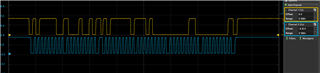
When I try to communicate with the OPT3101 however, I have some issues. The communication is working and there is an ACK off both side. I can read all the register, but they are not changing when I try to write a new value. I can see the data being transmitted and acknowledge with an oscilloscope and a logic analyzer.
I then tried to replace my Main MCU board by an Arduino UNO and it worked well. I then made few test using one after the other as I2C master for my OPT3101 PCB.
Here are the issues, lead I found:
- When I connect my oscilloscope probe (in 1x config) to the SDA line only when the chip is connected to the arduino, the registers are not updated when I change them. However, if I change the config in 10x on my probe, everything is working. If I connect both SDA and SCL, everything is working even in 1x configuration mode.
- The Arduino UNO works in 5V and has an internal pull-up by default. My main MCU work in 3.3 V and the SDA and SCL line are pulled up with 10K resistors. When I remove the internal pull-up resistor of the Arduino and pull the line to 3.3 it is not working anymore. But I still see the correct messages on my oscilloscope. When I add a resistor on my main MCU to pull the line to 3.6V, the register update correctly but randomly (not always). I thought that, it was because of the VIH of the MCU or the OPT3101 chip, but both are powered in 3.3V in my application, meaning that the VIH is around 2.3V which is low enough to detect a logic 1.
- When I use the Arduino and not my main MCU, the update could work sometimes even with the probe on the SDA in x1, but it was depending on the length and position of my wire.
I think that the problem is related to the capacitance of the I2C bus, but I followed all the design rules of the OPT3101, and it doesn't explain why the I2C com is sometimes working with the line pulled to 3.6V and not when pulled to 3.3V. I don't understand then where it comes from. Do you have an idea? Maybe it is something totally different?
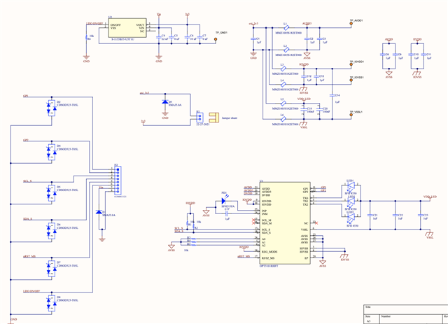
I attach below the schematics of the OPT3101 PCB that I designed. (The OPT3101 PCB is powered by 5V like my main board but the Main MCU and the OPT3101 are powered by 3.3V. There is an LDO on both boards)