This thread has been locked.

If you have a related question, please click the "Ask a related question" button in the top right corner. The newly created question will be automatically linked to this question.

AWR2243: TIDA020047 can't download appimage

Part Number: AWR2243
Other Parts Discussed in Thread: TIDA-020047, UNIFLASH

Tool/software:

Hi team,

I have a TIDA-020047 and it can't download appimage correctly.
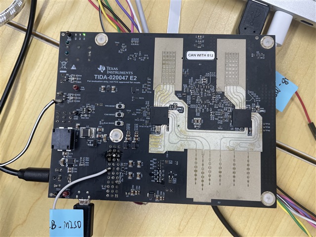
Regards,

Shawn

  • Please see below instructions

    1) Disable the watch dog timer

    2) Flash the image

    Disabling the watchdog.

    In this step, we disable the watchdog timer, but allow SPI communication. There are two ways to do this step, on with a jumper already present on the board or with a 1kOhm+ resistor. 

    Method 1: Using a jumper already present on the board.

    This method needs no extra component.

    1. Disconnect the power supply to the board.
    2. Connect the jumper J9, 3rd row (from the top) on the right side (E2 boards come with this already connected). This disables the watchdog.  
    3. Connect the power.
    4. Disconnect the jumper. This enables the spi communication (Chip Select is not pulled low). Watchdog remains disabled.


    Method 2: Using a resistor.

    Place a +1kOhm resistor in the J9,3rd row (chip select pin) instead of the jumper. This will disable the watchdog, while permitting SPI communication. This is easier, as no jumper needs to be connected and then disconnected every time the board is reset. 

    Flashing a binary image

    1. Move the jumper J6 from RUN to FLASH by moving it from the top position to the bottom position.
    2. Unzip the demo image (‘Two Chip Cascade Software Binaries for AM273x.zip’) to a folder, open cmd.exe to the same folder and use the following command (after moving J6 to the flash position) to flash the firmware. Note that there should be four files in the folder

    python  C:/ti/mmwave_mcuplus_sdk_04_04_00_01/mcu_plus_sdk_awr294x_08_06_00_28/tools/boot/uart_uniflash.py -p COM6 --cfg=demo.cfg

    Note that you should change COM6 to the user/application port number.

    1. Move jumper J6 back to RUN position.
  • Hi Zorah,

    In the forth picture, I have add a 1k resistance to disable WDT. And the jumper is moved to FLASH. But we can't download the appimage. And only D5 LED is working when the board is connected to power. What is the next step for debug?

    Regards,

    Shawn

  • What power supply are you using? Please make sure it is 12V. Also please make sure the COM port is updated correctly

  • Zorah,

    The power is 12V and COM port has been updated. You can see the first pic.

  • Hi Zorah,

    I have tested the output of LP876242, the 3.3V, 1.8V, 1.2V and 1.0V A are all normally. 1.0V B doesn't have output. For this buck, it should work after the appimage is downloaded and run. Need you to give us next debug step.

    Regards,

    Shawn

  • If you have tested the above debug steps and it still doesn't work, it means the board is broken. Please try on a different 2 chip cascade board