This thread has been locked.

If you have a related question, please click the "Ask a related question" button in the top right corner. The newly created question will be automatically linked to this question.

TMAG5170DEVM: Tuning sensor/target

Part Number: TMAG5170DEVM

Tool/software:

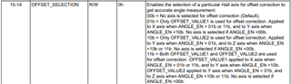
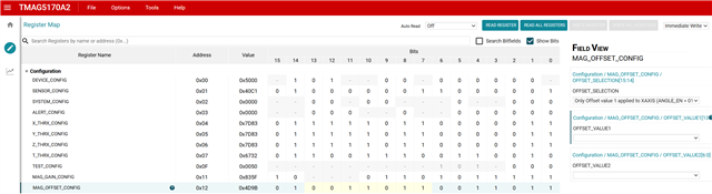
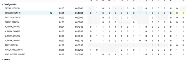
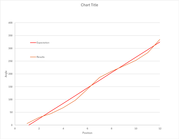
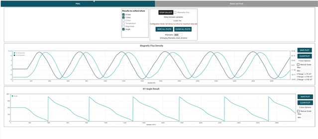
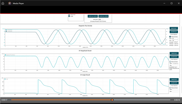
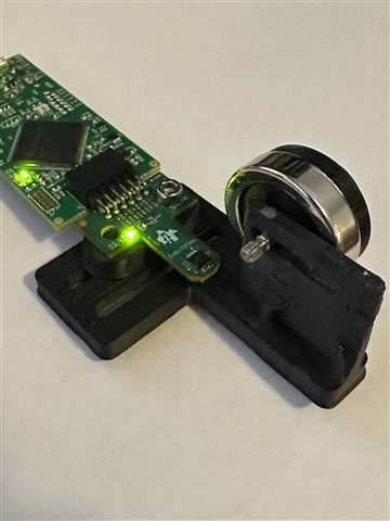
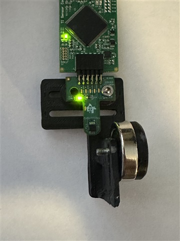
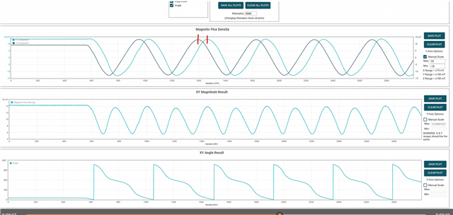
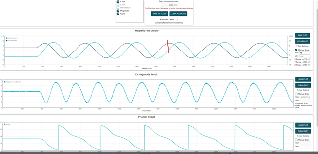
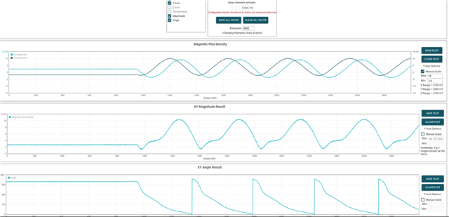
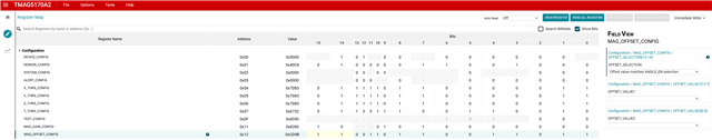
I have an off axis diametric magnet I am sensing position on.  Using the Angle_En - XY I am able to get a fairly decent response, but the response is not too linear, more sinusoidal.  I next began to adjust the sensitivyt of the X axis to +/- 75 and Y = 150.  This helped to reduce the error.  Next I adjusted the mag_gain_configs so that the XY outputs had the same magnitude, according to 8.2.2 Detailed Design Procedure.   I did not see an improvemnt in my results.  Is there something more I should be adjusting?  Do I need to be adjusting MAG_OFFSET_CONFIG?

  • Michael,

    Just to be sure, you should be targeting that the output codes of the device produce sinusoids with equal amplitude.  So having the two axes in different ranges can be used to correct in cases where there is a large disparity between them.  This procedure sounds correct if that is what you have accomplished.

    In the off-axis configuration, amplitude mismatch is usually the largest contributor to angle non-linearity.  In some magnets, the geometry can produce somewhat distorted sinusoids for the magnetic field input.  I have observed this to be the case when the sensor is placed quite close to large diameter ring magnets.  If this is the case, I would increase the gap between the sensor and the magnet.  Usually at larger distances the field will be closer to the ideal sine and cosine you are looking for.

    However, if amplitudes are matched and not distorted, then another possibility is to check that the sine and cosine signals are 90 degrees out of phase.  If there is orthogonality error (i.e. sensor is somewhat rotated relative to the magnet) you may see some phase shift.  This would also cause non-linearity in the angle measurement like you have described.  You might need to check your alignment.

    Besides these, I would also make sure any offsets are also cancelled out.  MAG_OFFSET_CONFIG should allow you to correct the axes used in the angle measurement.

    Thanks,

    Scott

  • What do you mean by below?  The default is MAG_OFFSET_CONFIG set to no axis selected.  Is this what you are recommending? 

    Besides these, I would also make sure any offsets are also cancelled out.  MAG_OFFSET_CONFIG should allow you to correct the axes used in the angle measurement.
  • Michael,

    There is a setting for how you want to apply offset correction.

    You can select to apply offset correction to the first axis, the second axis, or both axes used in the angle measurement.  I would recommend correcting offset for both to get the most linear result.

    Thanks,

    Scott

  • I think I'm inputting the bits wrong.  I am using XY angle output and want to do correcting offset for both. What i have did not improve my results.

  • Michael,

    You currently have a code of 0b01 selected for offset correction.  This will only apply the X axis correction in your case.  You will want to change this to 0b11 in order to correct both X and Y.  You'll can do a quick check after applying offset correction that:

    (MAX+MIN)/2 = 0

    Can you provide a capture plot of your results?  If you can export to a csv would be even better.

  • Can you give the code in bits I should have, I'm not getting that right.

  • Michael,

    0xCD9B should be correct.  You will see the drop downs in the "Field View" section update.  Right now you can see that for OFFSET_SELECTION it is indicating that only the X-axis is selected.  You may change the value using the drop down, by double clicking on any single bit you would like to change, or by changing the hex code all at once.

    Thanks,

    Scott

  • I was able to make those changes and then dial in the gains.  I don't think this made much of an improvement.   What would be the best way to share my setup/results?  Currently I am manually plotting 30 degree positions, see the second plot.

  • Michael,

    Is it possible to use the EVM GUI to capture a full rotation at as smooth of a rate than you can manage? In the plot for the XY magnetic field outputs you should see your sine and cosine signals.  If you can save the data from this plot, you should be able to attach it here and I could take a look.

    Thanks,

    Scott

  • is this what you're looking for?  I took a little fixed speed motor and used it to turn the magnet.

  • Michael,

    It looks like in your capture that the X component ranges from about +/-13mT and the Y component from somewhere around +/-30mT.  Since the Y component is more than 2X the X component range, you will have to attenuate Y. While on the plot the amplitudes look close, there are separate vertical scaling for each component.

    If we look at the ratio of the two axes (X/Y) we get a factor of something around 0.43

    Using this I would estimate that your gain correction factor should be 0.43*1024 = 444 = 0x1BC

    The entire register write would be = 0b1000 0001 1011 1100

    This is assuming that no other correction is currently active.  If you have gain correction already enabled, then you'd have to adjust for that correction already in place.

    Thanks,

    Scott 

  • I took the wrong screen grab, here the xy range are pretty similar.  Should this resolve the issue?  I thin this does not resolve the issue though?

  • Michael,

    Is your sensor rotated with respect to it's alignment with the magnet?  You should target having either the X or Y axis of the sensor orthogonal to the magnet.  It seems that your peak values of one axis do not align to the zero crossings of the other axis.

  • See below images on how the target/sensor are oriented


  • Michael,

    It looks fairly straight from the images, but the perspective can be a bit deceiving.  It looks though that the two main options for the sensor alignment to be off is if the EVM is rotated somewhat from straight since it is only connected with a single screw, or if the rotating magnet assembly has some tilt as it sits in the slot cut in the vertical edge. 

    You might try adjusting the position of the EVM slightly while the motor is spinning to see if you can get the phase between sine and cosine to get closer to ideal 90 degree separation.

  • I'll try and tighten things up a bit more.  

    Whats the easiest way to identify 90 degrees of separation?

  • You should be at a relative maximum on one channel while the other is at a zero crossing.

  • This is does seem a little better, I did my best to get the max/zero crossing aligned and adjusted the hardware.  I had the mag offset turned off here.

    Below I turned the magoffset on and the results are worse.  The XY Flux values shift to not center about 0, is that what should happen?  The second shot are my settings.

  • Michael,

    It is possible to set mag_offset in such a way that it will make the centering worse.  You will need to adjust to your specific code to get the optimal result.  I'm not sure the exact vlue you will need, but it can be calculated following this process:

    Thanks,

    Scott