Tool/software:
Hi Team,
My customer is looking at >50cm signal routed through low loss PCB material between ground plane as differential pair.
What would you expect the maximum range would be?
Kind regards,
Lucas W
This thread has been locked.
If you have a related question, please click the "Ask a related question" button in the top right corner. The newly created question will be automatically linked to this question.
Tool/software:
Hi Team,
My customer is looking at >50cm signal routed through low loss PCB material between ground plane as differential pair.
What would you expect the maximum range would be?
Kind regards,
Lucas W
Hello Lucas,
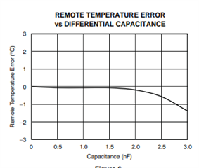
As the trace increases, resistance and parasitic capacitance increases. TMP422 can cancel up to 3kOhms on the D+ ad D- trace. The graph below shows how increasing parasitic capacitance can affect the error in the remote senor. As mentioned in Optimizing Remote Diode Temperature Sensor Design (Rev. A), tracing the D+ and D- through the PCB or using shielding in recommended. I liked that the customer is planning to trace the signal through the PCB. Proceed with the recommendations and the >50cm length and we can debug it from there.

Best Regards,
Meredith McKean