This thread has been locked.

If you have a related question, please click the "Ask a related question" button in the top right corner. The newly created question will be automatically linked to this question.

LDC0851: Sense distense and EMC issue

Part Number: LDC0851

Tool/software:

We mainly use LDC0851 as a position induction switch, a plastic hose with a small section of stainless steel metal sleeve on the pipe, need to identify whether the metal pipe is in position, the main problem on our side is excessive radiation and unstable working condition. Do the first version of the radiation beyond more, in order to improve this problem, on the antenna string 600R magnetic beads, radiation relative little improvement, made 50 pcb, a dozen pcb normal work, other state is not stable, work is not normal, the magnetic beads, or labeled 0R resistance, or work is not normal (when the induction state to metal light on, metal leave the light not go out, only with metal in the reference coil induction the light out). This abnormal work of pcb, we do not know whether the coil on pcb is not done well (the feeling is not enough or much), or we have a problem in circuit design, the attachment is our circuit prinV00.02.rarV00.01.rarciple diagram and PCB board layout, bother your FAE to help analyze, whether it meets the design requirements of LDC0851? Our target-sensing distance is 6mm.thanks very much!

  • Hello,

    I am not able to view the .sch and .pcb files you attached.  I tried opening the .sch in Altium, but just see a blank schematic.  Can you provide PDF's of the schematic and layout?

    Can you also provide more information on the type of radiation that you are failing?  Is this failing radiated emissions at the resonant frequency of your LC circuit?    

  • APS 1023-551-00.02.pdfAPS 1023-552-00.02.pdf Dear Eddie,  appreciate your fast reply and help. attached is the .sch and .pcb in pdf format. and also i attached the EMC test report.  优能拓 RE 2024.11.18.pdf

  • Hello Jason,

    In your schematic, the coils are labeled as 6.8nH.  Is this correct?  This is far below the minimum inductance of the device.  What is the resonant frequency of the LC tank circuit?  If the coils are truly 6.8nH with 56pF capacitance, the resonant frequency would be in the hundreds of MHz, which is also outside of the device specification.  


  • Dear Eddie,

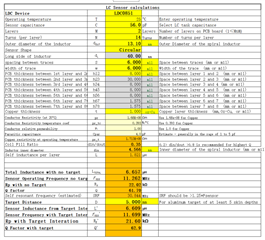
    Thanks for your reply.  Where you get 6.8nH?  according to our caculate, it's should be 6.657uH, see the attacehd picture, am i right? 

  • Hey Jason,

    Eddie's comment I believe stems from the following portion of the schematic.

    So if I could summarize your issues at a high level, one issue would be that the device does not trigger properly for around 76% of your boards, and the other issue possibly related to that first issue is excessive radiated emissions. I think a good starting step would be to measure your coils and verify their impedance for both the working and non-working boards.  With that we might have some more clues as to why your boards are exhibiting the symptoms you mentioned above.

    If you manage to get those measurements within the next day or so, you might not get another response until next week due to the holidays.