Tool/software:
Hi Team,
I would like to customize the .cfg parameters of the True Ground Speed Demo for my purposes. As a starting point, I am using the .cfg profile of conveyorbelt_belt_true_ground_speed from the SDK directory.
In the first step, I want to adjust the parameters for my test environment, such as Field of View, rangeSel, SensorPosition (and possibly others?).
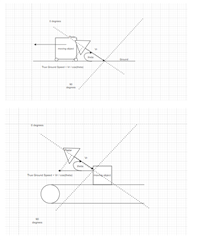
Question 1: The sketch from the Resource Explorer for both demos is identical in terms of the angle (Sensor Elevation). Why is 45° assumed in one case and 0° in the other, even though the position of the sensor is identical according to the sketch? 0° would mean that the sensor is attached at the end of the conveyor belt and "looks" into the travel axis of the conveyor belt.
Question 2: In the default setting, the parameter "presenceInfo" in guiMonitor is set to "enabled". I tried to add the parameter "mpdBoundaryBox 1 -1 1 0 1 0 1" in this context, but it doesn't work.
Question 3: Which other parameters should I consider to accommodate my desired application? Currently, the Industrial Visualizer only responds at higher conveyor belt speeds. Is calibration with a Corner Reflector necessary? So far, I haven't entered any correction values for "compRangeBiasAndRxChanPhase".
Thank you very much in advance and best regards