This thread has been locked.

If you have a related question, please click the "Ask a related question" button in the top right corner. The newly created question will be automatically linked to this question.

LDC1614: Wrap Around Noise

Part Number: LDC1614

Tool/software:

Hello there!

In the last few days I looked through this forum in order to help us with some issues we have with the LDC. This post is about an issue we call "wrap around".

First, our setup:

We have three coils arranged in such a setup. In the middle of it a copper rod is inserted. We use this setup to measure the thickness of the rod. It works surprisingly well.

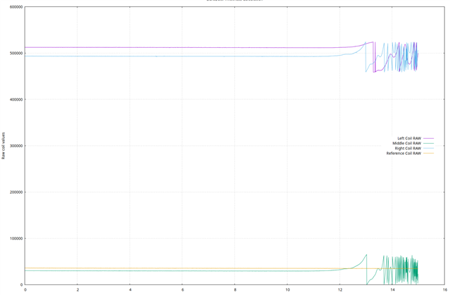
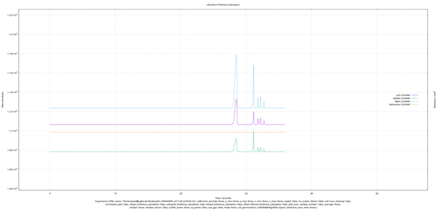
On to our issue: When the rod is cut in half (lengthwise) or placed off-center, we observe an issue that looks like an internal integer overflow or something similar happening:

This issue only seems to appear on the coil that is farthest from the copper. Interestingly, the distance between the coil and the copper in this scenario is in the same ballpark as the diameter of the coil.

We wonder if this is something that can be resolved via config, or if this is a design error. I played a bit with your LDC Calculator Tool and came to the conclusion that the SNR is really low in this scenario because we're almost in the flat part of the curve. This might be related to the observed issue and is something we want to fix in the upcoming version. However, this is still something we'd like to understand before proceeding.

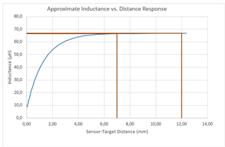
This is the tool's output when entering our worst case parameters. This might be related to the wrap around.

  • I want to add that deglitch is set accordingly.

  • Tim,

    The sensing distance that gives the best resolution is about 3% to 30% of the sense coil diameter. This would be the steepest part of your curve.

    You can sense up to 50% of the coil diameter, but with decreased resolution.  This would correspond to a separation distance that goes up to the beginning of the major "bend" in the curve.

    Some applications to determine only the presence of the target, but no other info, can work at up to 100% of the coil diameter. I'm guessing this corresponds to the part of your curve just before it flattens out. 

    You can find more discussion and examples in the app notes:

    1. LDC Sensor Design
    2. LDC1612/LDC1614 Linear Position Sensing

    Another app note covers drive current settings, which can help optimize performance:

    More information on LDCs can also be found at the [FAQ] Inductive sensing FAQ - Frequently asked questions page.

    Regards,
    John

  • Tim,

    One thing I forgot to mention...
    When we talk about resolution and distance, the implicit assumption is the target is a flat conductor at least as big as the sense coil. 
    I believe the equations used in the tool may be based on an infinitely large, flat target.

    Regards,
    John

  • Thanks a lot for that reply! I was already aware of most of the linked documents. It still helped me nevertheless.

    This image shows the result of our mapping between rod thickness and the measured output. It is already quite good if one considers that we're currently 8-12mm from the sensor away (depending on the rod distance).

    Everything you said so far points us in the direction that we should spend some time to test what happens with decreased distance and increased coil size.

    I do have on more question though: since the rod is a long rectangle when seen from the side, shouldn't a racetrack coil be beneficial here? The calculation tool doesn't show any improvement even though I expected one. This might be due to the fact that the copper surface is calculated as a infinitely large flat surface?

  • Tim,

    As a guess, I'd say a racetrack coil would be a good way to increase the coil area while (perhaps) keeping the height closer to the height of the rod. 
    The tool doesn't show any improvement because it is assuming the target geometry mentioned in my last post.

    Regards,
    John

  • Thanks a lot again! I guess we will have to try a few things then and see how the results look like

  • okay, as a first test we decreased the distance which indeed improved the results. The SNR improved - as expected - by a factor of 10. However, the wrapping issue still persists. One thing I noticed is that it happens where the inductance-distance curve flattens, see the highlighted part:

    Interestingly the wrapping is exactly 65536 (2^16) and we confirmed that it isn't a bug in our code. The LDC outputs these values. To me it seems like there is some kind of bug in the LDC when the metal object is far away (about 9mm in our case).

    We will further investigate this and try some different coils as well. But this needs some time. Due to the way the sensor will be used, the minimum distance will probably never be below 3mm. And since the rods can be up to 12mm thickness, in theory there can be up to 6mm of deviation. So a range of 3 to 9mm should be supported. My idea was to increase the size to 16 or even 18mm. This would improve the SNR even more. But our bigger problem, the wrapping, could still be there. Even when the coil is that much bigger and closer, the worst case scenario is still close to the flat area.

    In the meantime, is there some correlation between sensor stability for larger distances and the sensor frequency?

  • Tim,

    I'm not sure about a direct relationship between stability and frequency.

    Compare two systems, one with a lower frequency, and one with a higher frequency.
    All things being equal, a higher frequency will require a sense coil with a smaller inductance. 
    If the target is the same size and same placement between our two systems, then a small movement at a larger distance will cause a proportionally smaller change in the higher frequency system with a smaller inductor. 

    All that being said, what are your register settings for OFFSET, RCOUNT, and SETTLECOUNT?
    Have you tried varying these for the case of a larger separation distance?
    What are your sensor frequencies?

    Just so you know, we will be OOO for the Thanksgiving holidays, and will be back on Monday.

    Regards,
    John

  • That makes sense. Thanks!

    And this is how we set our parameters. It is identical for all four sensors. OFFSET is zero, therefore we didn't set anything and used the default.

    set_settlecount(&LDC1614Channel::CHAN0, 0xF);

    set_rcount(&LDC1614Channel::CHAN0, 0x38B);

    We increased rcount quit a bit but there was no improvement visible

    The sensor frequency is calculated as 1.9MHz, measured as 1.5MHz. Probably due to the parasitic capacitances in the coil.

  • Ok, we got some news. See the following image:

    We can now explain the wrapping, but we don't know why it happens. For this experiment I placed the three wrapping coils next to one another on a desk. Then I took a copper rod and slowly got closer. As you can see, the line in all three cases increases, until it suddenly jumps down before increasing again. This happens multiple times. The measurement stopped when we received amplitude errors at the end where the distance was almost 0. Samples with errors are not plotted by our tool, so this noise here is wrapping.

    I think we're doing something wrong here. Your application notes always showed scenarios with distances as low as 2mm where the metal object is moved horizontally. While the test in the image was a vertical test, we also performed horizontal tests with the same results.

    I think there has to be something wrong with our config parameters. But we checked everything that we could think of.

  • Tim,

    I don't understand the output gyrations you are seeing. 

    Not sure what to suggest next, other than to monitor the oscillator signal as you move the rod. 

    One trick we have found to be useful is to place a 1k leaded resistor between the probe tip and the test point on the PCB.
    Even high impedance oscope probes can load the output and cause distortion and freq shifts.

    Are the rods made of metal that can support a magnetic field, like iron or steel?
    Or are they made of non-magnetic metal, like aluminum or copper?

    Regards,
    John

  • Ostilloscope is something I will try, thank you! Also the 1k resistor idea sounds good.

    Right now we are verifying that we don't have the two bytes flipped, because the error we're seeing looks exactly like this. But so far out code seems good.

    It's a rod made out of copper, not hollow

  • Thx Tim.

    Let me know how it goes.

    Regards,
    John

  • we're pretty sure that our software is okay. We printed the bytes from the LDC and they looked correct. So we're as lost as before. But it is almost 9pm in Germany, we'll call it a day for today. Tomorrow I'll do some tests with the oscilloscope. I'll keep you posted.

  • Thx Tim.

    Everyone here in the US will be out tomorrow and Friday, and back in the office on Monday.

    Regards,
    John

  • That's alright. I think you told us everything you could. Enjoy your time off!

  • One thing we do wonder ist why are the 0 and 1 coil at a base value of 500.000, while the other two are at a base value of around 4000. Their range before wrapping is identical and MUCH lower to the difference in these two. All four coils lie next to each other on the desk. Even the cables are about the same length.

  • Tim,

    It sounds like the coils, connections, and device settings are pretty much identical.
    I think the next step would be to carefully measure the sensor waveforms for comparison at the base condition.
    Look at DC, frequency, waveform shape and pk-to-peak voltages.

    These devices are really just weird data converters, so this starts the troubleshooting by looking at the inputs.

    If everything looks identical (or almost), then its time to confirm device settings are what they should be.

    I wouldn't normally suggest this, but if the waveforms and device settings look okay, then it might be worth trying to reproduce your findings with an EVM  and the supporting GUI.

    What are you using for a reference clock?

    Regards,
    John

  • John, we got it working!

    This is the pendant to the previous image with the awful wrapping - now without.

    The issue was our fault, kind of. But so deep down, we completely missed it. The I2C peripheral was tasked to read the two 16-bit variables from the LDC. If one would see these two 16 bit variables as b3 b2 b1 b0 than only b3 and b1 were read correctly. b2 and b0 were random variables from the LDC's memory, hence the offset. But since we didn't look at the peripherals code and b3 with the status registers was the correct one, this issue went completely unnoticed. Yesterday when we connected an oscilloscope to the I2C bus we had an a-ha moment and started debugging the peripheral. And as you can see, we found the issue! This not only fixed the wrap around issue, but also a quantization bug be noticed.

    Thanks again for your time and effort, this was very appreciated!

    Your idea to approach it with the eval board and the GUI would have probably pointed us in the same direction, so thanks, that was a good idea.

    And just so you know, we use an 38.4MHz temperature compensated clock:

    Not sure if this is the best way to handle the clock voltage level shifting, but this is what I came up with and it works! :)

    Enjoy your time off