This thread has been locked.

If you have a related question, please click the "Ask a related question" button in the top right corner. The newly created question will be automatically linked to this question.

ISOTMP35: Information on application

Part Number: ISOTMP35

Tool/software:

Hello all,

I am on the process of the conceptual desing of a drive. In this drive I am planning to use TSC (top side cooled) MOSFETs. The whole package is roughtly 15mmx15mm and is a half bridge.

In previous designs, for the temperature measurement of the mosfets I have either used PT1000s or the integrated temperature sensor in the package of the transistor (mostly when I have worked with power modules).

For this design however, I wanted to do something different. 

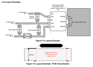
Since I am planning to have all the domains of the drive in one PCB board, and packaging size and simplicity are important, I was wondering if using a temperature sensor like ISOTMP35 and placing it close to my MOSFETs makes sense. In an application note from TI, I see that this type of sensor can also be used for GaN/SiC or Power Mosfets however, I am not sure how I would have to manage its placement with respect to this TSC MOSFET and if it is even advisable to use this sensor for such MOSFETs.

I have been trying to find application notes or documents (from TI) that touch upon this subject, but I haven't been able to find anything. 

So if anyone of you has used these sensors for such applications, has documents related to it, or any advice, I would really appreacite it. 

Thanks in advance,

K.K

  • Hi Kosta,

    Thanks for reaching out. Our team is currently working on creating this exact content, we should have at least one application note on the placement of ISOTMP released next year.

    What voltage is your MOSFET operating at, and what temperature levels are you trying to sense? For placing the ISOTMP35, it is best to place the ISOTMP35 along the isolation boundary (if possible), or route the low voltage ISOTMP35 output from the HV side to the LV side (while taking care not to violate creepage and clearance). I would try and connect the HV side of the ISOTMP35 as close as possible to your MOSFET, through a shared copper pad or plane. 

    Regards

    -Alex Thompson

  • Hello Alex,

    Thank you for your reply. 

    The operating voltage of the MOSFET would be between 400V and 800V (decision has not been made yet).
    I understand that at 800V might not be feasible to work with this sensor, looking at its isolation voltage, and at the same time 400V might be just at the limit, but for the evaluation board that I am currently trying to design this should not be a problem. The first (functionality) tests I can also do at lower voltages. 

    It is however something to keep in mind. With regards to that, is there going to be a re-inforced isolation version of this sensor? 

    The temperature levels I am trying to sense wouldb be between ambient temperature and 100-120 degrees celsius. 

    The plan is indeed to have this sensor placed on top of the isolation barrier, with its HV side on the HV domain and LV side on the LV domain of the board. 
    When you say to place the sensor on a shared copper pad or plane, does that mean that I can, for example, place the sensor on the HVDC+ copper plane of the board which would connect to the Drain of the MOSFET? Or am I not understanding this correctly?
    Would having this sensor placed on such a plane lead to any issues (being that the Tsense pins of the sensor are placed directly on HV which also exhibits voltage overshoots and noise due to switching)?

    Regards,

    Kosta Kotsis

  • Kosta,

    Thanks for the additional info. Yes our team is planning on releasing a reinforced version of ISOTMP35, that is currently being worked on by our team.

    Yes you can place the HV side of the ISOTMP35 directly onto the HVDC+ copper plane which the MOSFET drain connects to as well. Doing so is the main benefit of ISOTMP35. The direct copper connection allows for much more temperature sensing accuracy and faster response time vs trying to sense through PCB material.

    Yes voltage overshoots and switching noise is a concern, so we recommend the following layout:

    The load capacitor should be 1nF, and you will need to choose the right resistor and capacitor filter values to best filter the frequencies of noise you are anticipating. But the general strategy is to filter the output to reduce noise from CMTI and EMI.

    Regards

    -Alex Thompson

  • Hello Alex,

    Thank you. It is all clear now.

    One last question I had: Is there any date planned for the release of this re-inforced version of ISOTMP35?
    I am asking becasue I would like to know if this product will be available by the time I have a series production of this drive, which will be operating at a higher voltage (as mentioned before).

    Best regards,
    Kosta Kotsis

  • Hi Kosta,

    We anticipate releasing the reinforced version of ISOTMP35 early 2026 (this is subject to change of course). 

    Regards

    -Alex Thompson

  • Hi Alex,


    So the release should still take quite some time.
    Would you happen to know if this sensor can be used on a system that operates at 400VDC, or is that still too close to its limit.
    I understand that for a system working on 800VDC this would not be advisable.

    Regards,
    Kosta

  • Kosta,

    400VDC should be no problem at all, we have verified that the ISOTMP35 will work correctly to at least 700VDC.

    Regards

    -Alex Thompson