This thread has been locked.

If you have a related question, please click the "Ask a related question" button in the top right corner. The newly created question will be automatically linked to this question.

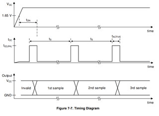
DRV5032: Does the sampling period vary as a function of VCC?

Part Number: DRV5032

Tool/software:

Hi!

We are using the DRV5032ZE.

In the data sheet table, the sampling period ranges from 13.3 to 75ms and the table data applies from VCC = 1.65 to 5.5V.

Is the nominal sampling period strongly correlated to or is a function of VCC?

In our design VCC = 3.3V. (Operating temperature is 15-30C)

If the sampling period is a function of VCC, can you provide any characterization data of what the nominal sampling period at VCC = 3.3V?

Thanks and Best Regards
Jerry Molnar

  • Hi Jerry,

    Thanks for posting to the sensors forum!

    I have reached out internally to see if there is any information we can share regarding this request.

    Best regards,

    Jesse

  • Hi Jesse,

    Thanks for your reply. I now have a related question.
    In our application we have a rotating cam with a magnet in it. Of course, we have to be turning slow enough so that that the sensor doesn't miss the magnet between sample. Kind of related to that is during the 40us active sample time, what is the response time of the sensor? This is not a parameter that is listed in the data sheet.
    I don't think it is an issue, but I would like to make sure that we don't have a case where the magnet is moving too fast for the sensor to respond.

    Thanks!
    Jerry

  • Hey Jerry,

    Output delay isn't specified for this device. How fast do you anticipate the magnet moving in your system?

    Best regards,

    Jesse

  • Hi Jesse,

    We're quantifying this now by measuring the angular velocity of the magnet location on the rotating cam.
    I don't have a number now, but I will in a couple of days. I know it isn't specified in the table, but is there a ceiling number estimate that would be "too fast"?

    Thanks
    Jerry

  • Hi Jerry,

    I think the possibility of missing the magnet would be more based on the amount of time the device is in it's sleep state during the period of magnetic sampling tS. The max period for the DRV5032ZE is 75ms. If we subtract out the typical active time period of 40us, the max sleep time is ~74.96ms.

    If the magnetic field can be presented and then removed in this time frame, then theoretically a transition could be missed.

    Best regards,

    Jesse

  • Hi Jesse,

    We're on the same page for the issue you described.

    In fact, we already got burned by it! The magnet was moving too fast and indeed, we were missing it.

    That experience lead me to ask the questions in the previous emails....such as:

    - does the 27ms-75ms sampling period spread apply at 3.3V?

    Thanks and Best Regards
    Jerry

  • Hey Jerry,

    Understood. I'm still waiting to hear back if we have any data regarding sampling period vs. Vcc.

    We do have some other Hall-effect switches that have a higher bandwidth/faster sampling rate, would either of these work for you?

    Are you able to share more details on the application? (i.e. the magnet/changing magnetic field you're trying to sense and the functionality you're trying to achieve with the Hall-effect switch?)

    Best regards,

    Jesse

  • Hi Jesse,

    Thanks! I will check those parts out.

    We're characterizing the angular velocity of the magnet embedded in the cam and should have results in a couple of days. I should be able to share info with you after that.

    For the moment we've changed the firmware re the way the motor is driven towards the expected end of the travel. The motor is being pulsed (kind of "bit banging" some "PWM"). That seems to work, but we have to get "under the hood" on some performance parameters (like the angular velocity and sampling period) to ensure that the solution will work over all variations of DRV sampling period, motor speed variation, etc.

    Best Regards

    Jerry

  • Hey Jerry,

    I see--so you're using the Hall-effect sensor to detect near end of travel of the cam to be able to alter the speed of the cam as it approaches the end of travel.

    Based on the speed of the magnet in the rotating cam, there have been cases where the switch misses the magnet and the speed of the cam ends up not being adjusted as it approaches the end of travel.

    Best regards,

    Jesse

  • Hi Jesse,

    Slight modification to what you wrote - we're using the Hall Effect sensor to detect the end of travel for the cam.

    The sensor only reacts when the magnet is right in front of it. We're now slowing the motor down as we get close to the end of travel (start to slow down based on time). By characterization, we know a couple of the units work with the slow speed we've chosen, but until we can quantify what the DRV5032 sample period is at 3.3V (that is a "nice to have"; we could fall back to the full data sheet limits) and the speed of the magnet (is it slowed down enough) can we engineer a solution that we know is good over all conditions.

    Best Regards

    Jerry

  • Hey Jerry,

    I think I understand now. Is it also correct that you are using the Hall effect sensor to define the end of travel? I.e. the end of travel in this case is not a physical end of travel (like the closing of a laptop lid). The cam is capable of rotating past/through the "end of travel", but the triggering of the Hall-effect switch is used to set the end of travel.

    For now I would design based on the datasheet limits, or check to see if any of the devices with a faster sampling rate improve performance.

    I know you previously mentioned you are testing the ZE variant of the DRV5032 (±63mT Bop max variant). Does this seem like the most appropriate magnetic threshold for your system? You may have already confirmed this--just thought I'd check.

    If not, our online magnetic simulation tool, TI Magnetic Sense Simulator (TIMSS) can help with simulating expected magnetic fields and device behavior: https://webench.ti.com/timss/ 

    Best regards,

    Jesse

  • Hi Jesse,


    Thanks for your reply. That is the application exactly.

    The magnetic work that was performed using a low sensitivity sensor and a strong magnet helped get us to the best solution for this application - i.e. the magnet has to be right in front of the sensor to trigger it.

    In any event, I'm still interested to hear if you get any more insight into the spread of sampling period vs VCC.

    Thanks!
    Jerry

  • Hey Jerry,

    Will do. I pinged again internally regarding any data we may have to share.

    Best regards,

    Jesse

  • Hi Jesse,

    Great, thanks! That will help us if you can snag some data.


    Best

    Jerry

  • Will do, I'll update this thread when I receive feedback.

    - Jesse