This thread has been locked.

If you have a related question, please click the "Ask a related question" button in the top right corner. The newly created question will be automatically linked to this question.

IWRL6432BOOST: IWRL6432BOOST - using UART

Part Number: IWRL6432BOOST
Other Parts Discussed in Thread: IWRL6432, SYSCONFIG,

Tool/software:

Hi Everyone,
 
I was wondering if someone could paste very basic steps required to get UART working? - ideally like 3 to 4 bullet points. If its much more complicated then also let me know - I might reconsider the approach.


I've looked into the docs but can't find exactly what needs to be done, and theres a few posts but they describe working with a UART example.

Right now I have python code on RPI which is clusterising point clouds to get range profile. This is from the level_sensing demo.

Imagine instead of using this over USB, I want to just get UART working. Which would be more robust and simpler. But if its way more work, its better to stick with USB.


1. Any physical changes needed? (some posts show just using jumpers into the connector?)
2. Any drastic code changes needed? Either on the RPI or on the Config (hard coded onto the IWRL6432)

Thanks!


  • Hi,

    We are looking into your query. Please allow us a couple of days to respond.

    Regards,

    Sharan

  • Hi,

    Could you take a look at the SDK driver example for UART present in MMWAVE_L_SDK_05_05_02_00\examples\drivers\uart

    This example is probably the easiest way to understand the entire UART transfer mechanism.

    Regards,

    Sharan


  • Hey,

    Can you explain in a bit more detail how you'd use this, just a high level overview.

    Because I can see it's setting up a function like UART, send bytes etc.

    But somewhere, im guessing, you'd have to establish the UART connection, what pins are going where.

    Then, this is in a drivers folder - when you build a project file, is there a drivers folder you can include and point to?

    So if you can give a couple pointers as to how the uart_echo example, could be used please

    Best,
    Fred

  • Hi,

    The drivers open function will open all the drivers which are enabled via Syscfg. You can also configure the PINS for each driver in the Syscfg file which is present in the project.

    Now, in terms of UART example, initially we have to create a uart transaction through UART_Transaction_init().
    Once done, this transaction has two main parameters buffer and count. Buffer points to the location where you want to store the received data(In terms of UART_read() ) or it points to the location from which UART_write() should take place. Count specifies the amount of bytes to be read/written per transaction.

    Once, these two fields are set, UART_read() or UART_write() can be called to perform the corresponding functionality. Both these methods have separate semaphores to indicate their completion.

    Regards,

    Sharan

  • Hey Sharan,

    Okay.

    Currently im using the level_sensing demo which uses functions from the radar toolbox like ParseUART etc. It is opening a USB UART COM port and parsing.

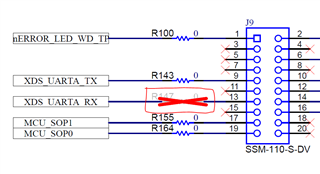
    In sysconfig I can see that UARTA is enabled, and from design files I can see this is used for the USB-UART linker over the MCU. And ordinarily the UARTA pins are below on J9: 

    What you are saying, is that in order to get these pins (or possibly use other pins on this header?) to transmit data, I need to call a couple functions:

    1. Open drivers 
    2. UART init
    3. UART read/write.

    Assume im using a raspberry pi (ubuntu) with GPIO UARTs exposed and confirmed to be working.

    What needs to happen, is I need to call those functions, on the Radar side right?
    So I need to put those into the mmw_cli.c file somewhere?

    Then I rebuild the project and the Radar will output over the pins. And in the UART driver file which we can include we can specify those pins.

    Is that all correct?

  • P.S - this Thread seems to contradict you:

    https://e2e.ti.com/support/sensors-group/sensors/f/sensors-forum/1091501/iwr1443boost-not-receiving-uart-signals-in-mmwave-demo?tisearch=e2e-sitesearch&keymatch=mmwave%2520UART#

    It implies that someone flashed the out of the box demo, and your colleague is instructing them to simply connect the relevant pins in J5 for RX and TX.

    In my case I've hardcoded a config so the RX and TX should be active as soon as the board gets power. It's just that I'm giving power through the Micro USB. so it might cause a UART port conflict but not sure.

    However what you were saying before means this above threads shouldn't be possible. It should only be possible for RX and TX data to get sent over that boosterpack connector Jx, if some firmware changes were made in those project files and then re-building.

    Awaiting your clarification

  • Hey Saran, 

    If you get time can you please check my reply

  • Hi Fred,

    There are two UART instances in IWRL6432, UART A and UART B. The default device settings in IWRL6432BOOST EVM allow you to establish communication through XDS110 interface using UART B. However, you can set UART A for communication if you want the data without a PC connection. In that case below points need to be considered:

    1. As UART A in pinmuxed with LVDS data lines, UART A and LVDS cannot be used together.

    2. To make the UART A data available at the J8/J9 connectors, required MUX/SWITCH settings will disable CAN connectivity.

    In sysconfig I can see that UARTA is enabled,

    From your statement, I assume UART A has already been set up as the communication interface. Below I am mentioning steps to make the data available at the J8/J9 connector:

    The data is available as the below signals, given the UART A is configured as the interface.

    S1.3 and S1.5 needs to be set to ON

    R190 needs to be depopulated.

    R147 needs to be populated. (From the snippet of your schematic, I assume this has already been done).

    [Optional]

    There are provisions to get the data from J8 also. In that case R77 and R118 need to be populated.

    I hope this answers your query.

    Thanks,

    Swarnendu

  • Hey,

    So besides switches, for the standard IWRL6432BOOST EVM - I'll need to de-solder R190? 


  • Fred,

    That is correct. In the EVM, XDS_UARTA_TX is connected to the XDS110 processor, which you would require to UNDO by de-populating the R190.

    Thanks,

    Swarnendu

  • Okay.

    There is no other easy way of using UART like UART B?


  • Hey Fred,

    If you want to use UART B, you can still receive the data over PC with default settings.

    It would be better for us to evaluate if you could explain more on how you like to get the data?

    The steps I shared are one time and you can perform them except you require LVDS connectivity.

    Thanks,

    Swarnendu