


Other Parts Discussed in Thread: AWR6843ISK
Tool/software:
hi josh,
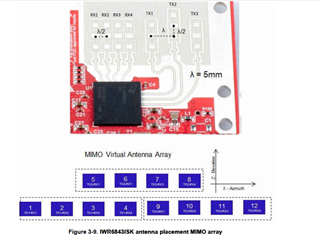
my requirement also running "Gesture_with_Machine_Learning demo " with AWR6843ISK EVM.
I have attached AWR6843ISK EVM mimo antenna array for reference:
the below code are taken from "C:\ti\radar_toolbox_1_30_01_03\source\ti\examples\Gesture_Recognition\Gesture_with_Machine_Learning\src\6443\mss\gesture.c file provided part of example design.
void Computefeatures_DOABased(void)
{
uint32_t *ptr;
cmplx32ImRe_t *DOA_Input_ptr;
int16_t rangeIdx, dopplerIdx;
cmplx32ImRe_t DOA_Input[gfeatures.numVirtualAntennas * 2]; // Need to account for the fact that there are 4 physical RX channels
/* Now find the largest value in the detection matrix in the first RANGE_BIN_END of range bins according to the MATLAB model
*
* In this target code, there are:
* 64 range bins
* 128 Doppler bins
*
* Search through the first RANGE_BIN_END range bins and across all Doppler bins
*/
gfeatures.rangeIndex = 0;
gfeatures.dopplerIndex = 0;
ptr = gfeatures.detMatrixData;
gfeatures.max_value_ptr = ptr;
for (rangeIdx = 0; rangeIdx < RANGE_BIN_END; rangeIdx++)
{
for (dopplerIdx = 0; dopplerIdx < gfeatures.numDopplerBins; dopplerIdx++)
{
if (*ptr > *gfeatures.max_value_ptr)
{
gfeatures.max_value_ptr = ptr;
gfeatures.rangeIndex = rangeIdx;
gfeatures.dopplerIndex = dopplerIdx;
}
ptr++;
}
}
gfeatures.currentWeight = (float)*gfeatures.max_value_ptr;
/* Use the range index and doppler index values to navigate to the location of 2D FFT Output samples */
DOA_Input_ptr = gfeatures.dopplerCubeData;
DOA_Input_ptr += (gfeatures.rangeIndex * gfeatures.numDopplerBins * gfeatures.numVirtualAntennas) +
(gfeatures.dopplerIndex * gfeatures.numVirtualAntennas);
/* Create an array for the 2D Input
* Since there are 4 physical RX channels on this device, this needs to be accounted for in the virtual samples array
* RX1 and RX4 values need to be multiplied by -1 to account for 180 degree phase difference between RX1 and RX2
* Also need to take into consideration the fact that the RX1 virtual antennas are separated by a factor of lamba and not lambda/2
*
* 2D FFT Data is organized in the following manner:
* [ 0 1 2 3 ]
* [TX1-RX1 TX1-RX2 TX1-RX3 TX1-RX4]
*
* Input data for the angle calculation will be organized in the following manner:
* [0 1 2 3 4 5 6 7]
* [TX1-RX1 TX1-RX2 TX1-RX4 TX1-RX3 0 0 0 0]
*
* This simplifies the HWA paramset set implementation since HWA can only zero pad and not zero fill
*
*/
#if defined(MMW_6843_ODS)
/* Populate DOA_Input with the four input samples from the 2D FFT Output */
// TX1-RX1
DOA_Input[0] = *DOA_Input_ptr;
DOA_Input_ptr++;
// TX1-RX2
DOA_Input[1] = *DOA_Input_ptr;
DOA_Input_ptr++;
// TX1-RX3
DOA_Input[3] = *DOA_Input_ptr;
DOA_Input_ptr++;
// TX1-RX4
DOA_Input[2] = *DOA_Input_ptr;
/* Apply the Phase Correction coefficient to the RX1 and RX4 values */
/* The 6843 ODS Antenna has RX1 and RX4 fed from the opposite side so all
* corresponding virtual RXs channels need to be inverted by 180 degrees
*/
// TX1-RX1
DOA_Input[0].imag *= PHASE_CORRECTION;
DOA_Input[0].real *= PHASE_CORRECTION;
// TX1-RX4
DOA_Input[2].imag *= PHASE_CORRECTION;
DOA_Input[2].real *= PHASE_CORRECTION;
/* Scale the 2D FFT input values down by 2^6 (64) */
// TX1-RX1
DOA_Input[0].imag = DOA_Input[0].imag / 64;
DOA_Input[0].real = DOA_Input[0].real / 64;
// TX1-RX2
DOA_Input[1].imag = DOA_Input[1].imag / 64;
DOA_Input[1].real = DOA_Input[1].real / 64;
// TX1-RX3
DOA_Input[3].imag = DOA_Input[3].imag / 64;
DOA_Input[3].real = DOA_Input[3].real / 64;
// TX1-RX4
DOA_Input[2].imag = DOA_Input[2].imag / 64;
DOA_Input[2].real = DOA_Input[2].real / 64;
/* Fill in the remaining values */
// TX2-RX1
DOA_Input[4].imag = 0;
DOA_Input[4].real = 0;
// TX2-RX2
DOA_Input[5].imag = 0;
DOA_Input[5].real = 0;
// TX2-RX3
DOA_Input[7].imag = 0;
DOA_Input[7].real = 0;
// TX2-RX4
DOA_Input[6].imag = 0;
DOA_Input[6].real = 0;
#endif
#if defined(MMW_6843_AOP)
/* Populate DOA_Input with the four input samples from the 2D FFT Output */
// TX1-RX1
DOA_Input[3] = *DOA_Input_ptr;
DOA_Input_ptr++;
// TX1-RX2
DOA_Input[2] = *DOA_Input_ptr;
DOA_Input_ptr++;
// TX1-RX3
DOA_Input[1] = *DOA_Input_ptr;
DOA_Input_ptr++;
// TX1-RX4
DOA_Input[0] = *DOA_Input_ptr;
/* Apply the Phase Correction coefficient to the RX2 and RX4 values */
/* The 6843 AOP Antenna has RX1 and RX3 fed from the opposite side so all
* corresponding virtual RXs channels need to be inverted by 180 degrees
*/
// TX1-RX1
DOA_Input[0].imag *= PHASE_CORRECTION;
DOA_Input[0].real *= PHASE_CORRECTION;
// TX1-RX3
DOA_Input[2].imag *= PHASE_CORRECTION;
DOA_Input[2].real *= PHASE_CORRECTION;
/* Scale the 2D FFT input values down by 2^6 (64) */
// TX1-RX1
DOA_Input[3].imag = DOA_Input[3].imag / 64;
DOA_Input[3].real = DOA_Input[3].real / 64;
// TX1-RX2
DOA_Input[2].imag = DOA_Input[2].imag / 64;
DOA_Input[2].real = DOA_Input[2].real / 64;
// TX1-RX3
DOA_Input[1].imag = DOA_Input[1].imag / 64;
DOA_Input[1].real = DOA_Input[1].real / 64;
// TX1-RX4
DOA_Input[0].imag = DOA_Input[0].imag / 64;
DOA_Input[0].real = DOA_Input[0].real / 64;
/* Fill in the remaining values */
// TX2-RX1
DOA_Input[4].imag = 0;
DOA_Input[4].real = 0;
// TX2-RX2
DOA_Input[5].imag = 0;
DOA_Input[5].real = 0;
// TX2-RX3
DOA_Input[7].imag = 0;
DOA_Input[7].real = 0;
// TX2-RX4
DOA_Input[6].imag = 0;
DOA_Input[6].real = 0;
#endif
/* Transfer DOA_Input samples to HWA Memory Bank M0 and prepare to execute HWA paramsets*/
memcpy((void *)gfeatures.HWA_base_address, (void *)&DOA_Input, sizeof(DOA_Input));
/* Zero out the selected index in the detection matrix for the next loop */
// gfeatures.detMatrixData[max_value_index] = 0;
*gfeatures.max_value_ptr = 0;
}
my question:
1. can you tell me , code changes required inside "void Computefeatures_DOABased(void)" function for AWR6843ISK EVM(as you mentioned all the three TX antennas are enabled to generate the above Virtual array pattern)
Regards,
mani

