Other Parts Discussed in Thread: SYSCONFIG, IWR1843AOP
Tool/software:
Hi,
By using the AWR1843AOP sensor we want to make an electronics card. In this application there will be a GPIO interface using 2 pins. For this aim we can use GPIO_0&1. But some points made us conflict. Can you please check and let us know the details?
First of all we couldn't understand why pin numbers are different?
From the technical datasheet of AWR1843AOP we see that GPIO_0's Ball Number is M2. But in SysConfig application there used J13, H13 like notations where in reality there are no Ball Numbers on the sensor. (Please note, we use SysConfig application with IWR1843AOP.)
Can you please share the SysConfig user guide?
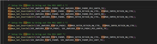
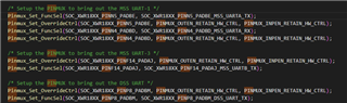
Why GPIO_0&13, GPIO_1&16 and GPIO_2&26 are using the same pin? Can you please clearly explain? Actually we spose that most probably for the applicaiton we use it will be better to select GPIO13 rather than GPIO0 or just opposite and for 1&16 and 2&26 pairs as well, and it will be selected as GPIO0 or GPIO13 then. And so on.
Finally:We guess that there is no restriction for us to use GPIO 0 & 1 at our board.
Can you please check if there is an important point we have to consider? (As you guess because of some uncertain points we wanted to mention this point in detail.)
Sincerelly,
Sercan