This thread has been locked.

If you have a related question, please click the "Ask a related question" button in the top right corner. The newly created question will be automatically linked to this question.

IWRL6432BOOST: Error: "The initial (idle) state of the CLK line does not match the settings" when obtaining raw ADC data through SPI from Logic Analyzer

Part Number: IWRL6432BOOST
Other Parts Discussed in Thread: IWRL6432

Tool/software:

Hi TI Experts,

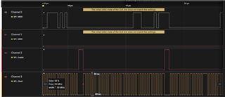
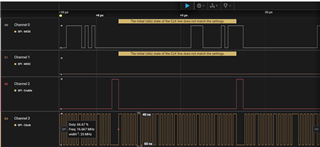
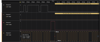
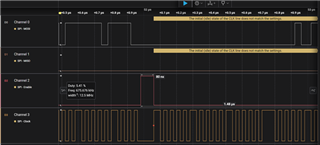
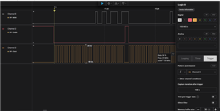
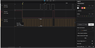
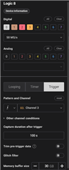
I have been evaluating the IWRL6432 mm Wave sensor for one of our applications, I wanted to obtain raw ADC data from the sensor using SPI through a Salae Logic 8 Analyzer. I followed the instructions as provided by your guide in the following link SPI Data Capture Users Guide. My Logic Analyzer could obtain a max sample speed of 50MS/s, The settings for my logic analyzer for obtaining SPI data are shown in below figures. I'm getting binary data but in some areas of the MOSI waveform, it gives an error showing "The initial (idle) state of the CLK line does not match the setting" at several areas of the entire waveform, although data comes during rest of times, I'm uncertain of the reliability of the data.

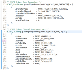
  • I used the source code provided in the radar toolbox with path ti\radar_toolbox_2_20_00_05\source\ti\examples\Fundamentals\xWRL6432_Raw_Data_Over_SPI and made the changes by defining the macros SPI_DATA_STREAMING to 1 and SPI_DATA_STREAMING_MODE to 2 for logic analyzer.
  • I flashed the program to the radar using the visualizer tool.
  • I pasted the configuration in the path ti\radar_toolbox_2_20_00_05\source\ti\examples\Fundamentals\xWRL6432_Raw_Data_Over_SPI\chirp_configs\xwrl6432boost named MotionDetect_SPI_Data_Capture_LA.cfg to tera term after connecting to the XDS110 UART COM port.
  • I started capture in logic analyzer and issued sensorStart 0 0 0 0 command after sending all previous configurations to the iwrl6432.
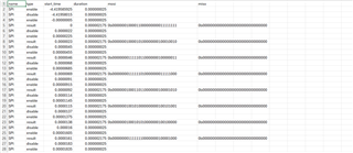
  • I receive the waveforms as follows

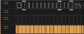
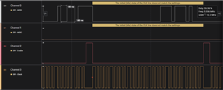
Why this error shown in above image occurs?

  • Are these steps that I followed for obtaining SPI data correct or is there anything I'm missing here?
  • Is the cause for this issue due to the fact that 50MS/s sample speed of my logic analyzer too low for this if so, are there any solutions such as lowering the SPI bitrate as such?
  • Is this error occurring due to some other issue maybe configuration file or source code.

Your support in this is much appreciated.

Thanks

  • Hi,

    The steps that you are following are correct. Could you check if the SPI connections are done properly and the corresponding channels are present in Logic Analyzer.

    In addition, 50 MS/s might be a bit low considering the SPI frequency. It's better if you could test the same with a higher sampling rate.

    Could you hover over the clock and tell me the out frequency as well?

    Regards

  • Hi Sharan,

    Thank you for assisting. SPI connections are all good, it seems the clock pulses are not consistent during transfer of 32-bit data packets, figures of the clock waveform are as follows,

    I can increase the sample speed of my Logic Analyzer to maximum of 100MS/s only if I turn one of the channels off (for example MISO). I tried that as well images are below.

    If the reason for this problem is the low sampling speed, is there a possible way to solve this by some changes to SPI settings in code without effecting the ADC data to adjust for 50MS/s sample speed of the logic analyzer. If not, could I obtain the 1d-fft or 2d-fft data with reduced SPI bitrate to adjust for the same sample speed 50MS/s.

    Thank you.

  • Hi,

    The clock frequency is about 25MHz. The logic analyzer connections are properly established, I think the issue is with sampling speed of the Logic Analyzer, since when I lowered the bitrate of SPI to 15000000 from 25000000, the error disappeared, what are your thoughts on this, does lowering the bitrate has any effect on the ADC data received or will data be lost.

    Thank you.

  • Hi,

    No, lowering the bitrate will not affect the data capture as long as sufficient frame periodicity is specified in the configuration. Higher bitrate is only specified for faster data transfer.

    Regards

  • Hi,

    Thanks for your help, so if I'm not mistaken, the data is transferred through SPI per chirp frame in the inter frame period right. Can you provide some way of calculating whether my frame periodicity is sufficient and within limits for my bitrate.

    Thank you.

  • Hi,

    The SPI transfer will depend on the type and the size of the data which you are trying to transfer. If you are trying to send max ADC Data(~96KB), the default frame periodicity of around 250-300ms should be sufficient enough.

    Regards

  • Hi, Sharan

    I obtained some Raw ADC data using the lowered bitrate, this is the chirp signal configuration which was used

    sensorStop 0
    channelCfg 7 3 0
    chirpComnCfg 8 0 0 256 4 28 0
    chirpTimingCfg 6 63 0 75 60
    frameCfg 2 0 200 32 250 100
    guiMonitor 2 1 0 0 0 1 0 0 0 0 0
    sigProcChainCfg 32 2 1 0 4 4 0 15
    cfarCfg 2 8 4 3 0 12.0 0 0.5 0 1 1 1
    aoaFovCfg -60 60 -40 40
    rangeSelCfg 0.1 12.0
    clutterRemoval 0
    compRangeBiasAndRxChanPhase 0.0 1.00000 0.00000 -1.00000 0.00000 1.00000 0.00000 -1.00000 0.00000 1.00000 0.00000 -1.00000 0.00000
    adcDataSource 0 C:/ti/mmwave_lp_sdk/examples/datapath/common/testBench/major_motion/adc_data_0001_CtestAdc6Ant.bin
    adcLogging 2
    lowPowerCfg 0
    factoryCalibCfg 1 0 40 0 0x1ff000
    mpdBoundaryBox 1 0 1.48 0 1.95 0 3
    mpdBoundaryBox 2 0 1.48 1.95 3.9 0 3
    mpdBoundaryBox 3 -1.48 0 0 1.95 0 3
    mpdBoundaryBox 4 -1.48 0 1.95 3.9 0 3
    sensorPosition 0 0 0.186 0 0
    minorStateCfg 5 4 40 8 4 30 8 8
    majorStateCfg 4 2 30 10 8 80 4 4
    clusterCfg 1 0.5 2
    profileSwitchCfg 0 25 25
    sensorStart 0 0 0 0
    I took data for 100 frames and dumped them to a csv file, the data is as shown in figure below
    So, when sending max ADC data at 250ms frame periodicity what could be the total number of rows of data which could be obtained in this csv file, each row has 32 bits, in this csv file I get 2457600 rows for 100 frames, could you please verify whether this is correct. What could be the size of the final parsed data array considering each 32bits as two signed int 16 values?
  • Hi,

    Yes, this is correct. If you consider it as two signed int16 values, then for 100 frames, you'll have 4915200 entries, where each entry is a signed int16

    Regards