Because of the holidays, TI E2E™ design support forum responses will be delayed from Dec. 25 through Jan. 2. Thank you for your patience.

IWRL6432: About the antenna size

Part Number: IWRL6432

Tool/software:

Hi,

Our original design was based on IWRL6432LAOP. Now, due to the issue of supply time, we may have to change the original design to one based on IWR6432.

In order to be compatible with the original molds, could you please given us some advices:

1. what the minimum size the antenna of IWR6432 can be reduced to? we need to make it as compact as possible, like:
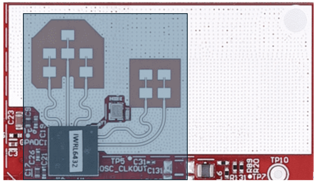
2. which antenna should be used as the center of the array?  The spherical radome is used in the original design.

3. what issues should we pay attention to when moving from AOP to an non-aop version?

Thanks

Guolong Zhang

  • Hi,

    We are looking at your query. Please allow us a couple of days to respond.

    Regards

  • Hi Guolong,

    1. what the minimum size the antenna of IWR6432 can be reduced to? we need to make it as compact as possible, like:

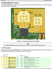
    The size of antenna depends on the operating frequency, bandwidth and the stack up used for the design. TI's 6432BOOST EVM is optimized for 62GHz operating frequency, 4GHz bandwidth and uses Isola FR408HR (Dk=3.24 @ 60GHz) 5 mil Core PCB substrate for antenna layer. The antenna size would not change by much and should be of similar size. The recommendation would be to re-use TI antenna design and stack for optimized performance. I would also recommend you go over the Layout Guideline of the below Hardware design guide for better understanding. 

    https://www.ti.com/lit/zip/spradl1

    Below is the training for Antenna Design, which should answer most of your queries.

    Antenna Design (For conceptual understanding of antenna design)

    2. which antenna should be used as the center of the array?  The spherical radome is used in the original design.

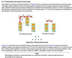
    The virtual antenna array for antenna used for 6432BOOST should be as below. The spherical radome should be placed in geometrical center the of the below shown virtual array. However, the actual location would depend on distance between the RX and TX antennas. If the same antenna design as in 6432BOOST EVM is used, the geometrical center would be closer to TX1 antenna patch element (center of radome would be between RX3 and TX1, however closer to TX1).

    3. what issues should we pay attention to when moving from AOP to an non-aop version?

    We should be careful about the DK and DF of the PCB substrate used for antenna layer in the stack up, as well as the 50Ohm impedance matching during Package to PCB transition for RF traces and the antenna patch element dimensions. Layout guidelines in the below design guide covers regarding these topics in detail.

     https://www.ti.com/lit/zip/spradl1

    More details about antenna for 6432BOOST can be found section 6 of below EVM user guide.

    Regards

    Ankit

  • Hi Ankit

    Thanks for your quick and thorough response. 

    Guolong