AFE3010: Test-Reset and Solenoid Operation.

Part Number: AFE3010
Other Parts Discussed in Thread: INA186

Tool/software:

Hi Team,

I have a question regarding Test- Reset button and solenoid operation. 

1) Could you please tell me if the button used at PTT is for test, how can we do reset? If reset is done with the same pin (PTT), can you please help us understand its mechanism.  

    How it is different from SW_OPEN pin. 

3) Can you please explain how PH and SCR_TST pin works.

4) Also, what modification is done if we use a relay in place of solenoid? Should it be Normally open (NO) or Normally closed (NC)?

    (Relay would be of SPDT type, with coil voltage 24Vdc and contact voltage 120Vac.)

5) Can you please provide a flow chart if NO relay is used.

    As per the datasheet (Fig 19 & 20), a single gate pulse is given during actual fault. After this single pulse, will SCR turned off?

    How will a NO relay remain energized after SCR is turned off

Looking forward to hearing from you.

  • Hello Cherished Engineer,

    I will respond to your question shortly.

    Sincerely,

    Peter

  • AFE3010-scr-latch-circuit.TSCHello,

    1) The functions of PTT and SWOPEN are shown in Figures 11 through 14 of datasheet. They both can "reset" the AFE3010 by resetting the internal digital Fault Counter, which needs to be done any time the AFE3010 detects a ground fault or fails a self test. 

    The main difference between them is that PTT pin also performs a single self test using FT pin and SCT_TST pin (if SEL=GND). If this self test passes, then AFE3010 will fire SCR. This part may seem counterintuitive because SCR is fired for ground faults, but the AFE3010 was designed so that in order to reset the entire GFCI receptacle there would need to be a logical connection (usually mechanical) between PTT and the load switch. So once PTT is pressed and passes self test, the SCR being fired would actuate the solenoid and allow user to mechanically latch close the load switch.

    However, this is not the only way to close the load switch (reset the GFCI). A microcontroller can be used to monitor signals and make a determination to open/close load switch relay.

    Overall, the reason for all of this is safety. If the AFE3010 is failing a self test (damage) or it needs it Fault counter reset, then the load switch should not be closed without running another self test (via PTT), which passes, or without resetting the fault counter. Note that whenever fault counter is reset, device will perform a self test every 180 line cycles as usual.

    3) PH pin is simply an input pin that is clamped to AFE3010 GND and VDD rails. It monitors for line zero-crossings to determine line frequency and act a clock.

    SCR_TST has the same circuitry as PH and also monitors for zero-crossings, but its main purpose to is perform the self test of SCR by checking for SCR continuity every line cycle. It can be turned off by floating the SEL pin. If SEL is floating, then SCR_TST can simply be shorted to PH pin.

    4,5) A relay can be used in place of a solenoid + load switch; however, the AFE3010 was designed so that SCR only fires single pulse so a latching circuit would be needed.

    If using a relay in place of solenoid, load switch combination, then the safest option would seem to be normally open, but a normally closed could be used as well given it is similar to any GFCI powering up with a closed load switch.

    There are two critical things to design for with relays: one is the power source for relay input coil, which is going to require mA of current usually. You will need to create a separate 24V rail that can source this coil current without droop. It is possible to power AFE3010 with a 24V source provided some current limiting between 24V and VDD pin (which are tied to an internal 20V Zener regulator).

    The 2nd critical design aspect is how to create the latching behavior as I mentioned above.

    This could be done with a MCU monitoring PTT, SCR, and/or SWOPEN. One example, is that any time SCR fires, the MCU will detect this and then also generate a latching signal that keeps relay latched. If user want to reset GFCI, they can press PTT and if MCU detect that PTT is low and that SCR fires right after, it would then release the latch signal and then close the relay. Please know that the AFE3010's GND is floating when powered off a full-bridge rectifier as shown in datasheet typical schematic, thus the MCU would need to be floating as well, or if MCU was referred to a 0V ground, then isolators would be needed to interface with monitored signals of AFE3010. Thus it is crucial to decide whether an MCU will be used or not, and whether the MCU will be 0-V referenced or referenced to AFE3010 ground.

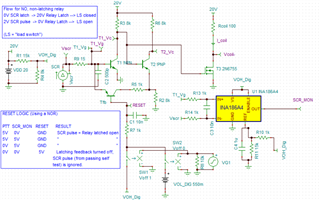
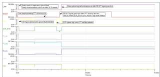
    The other latching solution is analog and requires additional latching circuitry. I have attached one example I made with a normally open 20-V relay that could be adjusted slightly for a 24V relay. Also, this solution provide additional circuits/logic to allow user to close the relay with PTT. Latching circuit requires 1 npn, 2 pnp, 4 resistors (to create the latching circuit off SCR), then a FET to toggle the relay's coil current.

    Additionally there could be a 2-channel NOR component that takes in a SCR_MON and PTT signal to create a logic level that controls enables/disables the latching circuit allowing user to close relay with PTT. The INA186 is used to invert the SCR signal into SCR_MON. I admit there should be an easier way to invert SCR, perhaps with a npn off SCR and monitoring collector voltage.. Perhaps the PTT pin could be inverted with BJT as opposed to inverting SCR. Either way, the primary purpose of this circuit is to show that you can create an analog latching circuit from SCR to relay AND that you can use NOR logic to allow user to press PTT to perform self test, reset AFE3010, and then close the relay.


    Please post back with any other questions.

    Sincerely,

    Peter