This thread has been locked.

If you have a related question, please click the "Ask a related question" button in the top right corner. The newly created question will be automatically linked to this question.

AWRL6844EVM: CANFD communication in low power mode

Part Number: AWRL6844EVM
Other Parts Discussed in Thread: AWRL6844, SYSCONFIG, AWRL6432

Tool/software:

Dear TI.

I would like to get some guidance on how to do CANFD communication in low power mode.

I implemented it using the example(mmwave_demo), but the following problems occurred.

When configuring CAN FD communication in Low Power Mode, EVK stops operating after one operation.

The same phenomenon occurs even if only communication is set without CAN Tx and Rx.

In normal power mode, CAN communication is performed well.

EVK will work fine in low power mode if CANFD is not configured.

[Configuration environment]

EVK : AWRL6844 (PROC182 REV A)

SDK : mmwave_l_sdk_06_00_02_00

DEMO : "mmwave_demo"

SYSCONFIG: 

EVK Switch : S1.1 Switch Off (STAN-BY-Mode Disable)

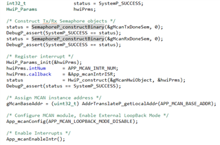
CANFD communication settings are configured with reference to Example "mcan_external_read_write"

CAN configuration is implemented within the DPC_init() function.

Best Regards.

J.Soo

  • Hi,

    Thanks for reaching out to us over E2E. Please allow us a day or so to provide a response.

    Thanks,
    Kundan

  • Hello ,

    It has been a while. Could you please provide quick help to customer? Your help would be appreciated.

    Regards,

    Victor Park

  • Hi Victor,

    I have assigned this thread to one of our software engineers. He will be able to respond within a day.

    Thanks,
    Kundan

  • Hello,

    Thank you for reaching out over E2E regarding this issue. First of all, I would recommend updating to the latest SDK, 06.00.03.00, if you haven't already to ensure that you are on the most stable version. Deep sleep does not support the usage of peripherals since all power domains, except for the Always On (AON) power domain. For now, you would have to take the idle state if you want to still access the CAN transceiver. 

    Regards,

    Kristien

  • Yes. After updating the SDK, I will test it again and let you know.

    In the LPM of AWRL6432, the CAN transiver worked by opening and configuring it every time it wake up from deep sleep mode

    If it must be in the idle state, does that mean that CAN communication cannot be worked in LPM mode?
    Even if I set up CAN communication again after wake-up, it cannot be used?

  • Hello,

    I apologize for any confusion here as I misread your question. I had assumed you wanted to use CAN communication during LPDS, but if you want to use CAN communication after LPDS, you will need to enable the CAN clock and re-initialize the transceiver upon exiting LPDS. These should both be done within the power_LPDSresumehook function - assuming you have already defined since the Power driver references this function by default. 

    For the CAN clock, you can call the following sequence within the power_LPDSresumehook function:

    PRCMPeripheralClkEnable(0, PRCM_GATE_CLK_ENABLE);
    while(PRCMPeripheralStatusGet(0) == 0U);

    If you haven't already, I would recommend creating a function similar to App_mcanConfig from the LSDK6 MCAN External Read Write example which initializes and configures various control registers of the CAN transceiver. This can then be called after the CAN clock has been re-enabled.

    Regards,

    Kristien

  • Hello ,

    I'm upgrading the SDK and testing it using the mmwave_demo in version 6.0.3.

    And, I added the code following your guide.

    However, it still works once and stops.

    It seems to stop when re-configurating the CAN communication in the LPDSresumehook function.

    If I remove the CAN configuration code, the LPM mode works fine.

    Is there a way to debug in LPM mode?

  • Hello,

    Could you share the code you currently have in your power_LPDSresumehook function? If you call any custom functions during the resume hook, such as a function similar to App_mcanConfig, could you also provide the code for that? 

    I should've asked earlier, but when the EVM is no longer operational, are you unable to reconnect to the debugger or are you able to connect but the device has faulted in some way? If you are unable to connect to debugger after LPDS, that would imply the device is still in LPDS since the JTAG connection would be disconnected during this state.

    If you are able to reconnect but the device has faulted, I would recommend setting a while loop with a variable that's always set to 1 or TRUE in the Power_sleep function around line 710 under <MMWAVE_LSDK6_INSTALL_DIR>/source/drivers/power/v0/power_xwrLx4xx.c. This can be used to halt the LPDS recovery sequence before resuming it by changing the variable value to 0 or FALSE in the Variable view of CCS. You can then step line by line through the recovery and see if there are any issues.

    Regards,

    Kristien

  • Hello,

    thank you for your kindly replay.

    1. I will share the code via link : Code 

        CAN_INITIALIZE function is called after DPC_init function in power_LPDSresumehook functinon   

    2. There is not other custum functions except CAN_INITIALIZE function in in power_LPDSresumehook functinon .

    3. After the EVM is no longer operational, I can not reconnect to the debugger. It seems like EVM does not wake up from sleep mode.

    I'm on holiday next week, so I think I am able to respond to your reply after two weeks.

    I ask for your understanding.

    Best Regards,

    Soo

  • Hey Soo,

    Thanks for sharing your code and answering my questions. In the future, you can add code directly to the post by clicking Insert -> Image/video/file in the text window. 

    3. After the EVM is no longer operational, I can not reconnect to the debugger. It seems like EVM does not wake up from sleep mode.

    It is likely still in sleep mode if the debugger is no longer connecting. Let me look into your code, and I'll get back to you at the start of next week.

    Regards,

    Kristien

  • Hi Christian

    It would be grateful if you could share your progress.

    I will wait for your answer.

    Best Regards,

    Soo

  • Hey Soo,

    I would recommend you do the following so I can debug this further:

    1. Load your program in CCS
    2. Within the Power_sleep function under <MMWAVE_LSDK6_INSTALL_DIR>/sources/drivers/power/v0/power_xwrLx4xx.c, set a breakpoint on line 687 and run your program
    3. Upon hitting the breakpoint which should occur whenever the device attempts to enter LPDS, check the following addresses using the Memory Viewer in CCS:
      0x5A04041C
      0x5A040014
      0x5A040430
      0x5A040434
      0x5A040438
      0x5A040670
      0x5A040674
      0x5A040678
      0x5A04067C

    Please send over a copy of all those addresses in a text file so that I can parse them and provide additional advice.

    Regards,

    Kristien

  • Hi Christian,

    I upload the memory values of the address.

    Format : 32-bit Hex - TI Style
    
    0x5A04041C	00000003
    0x5A040014	000F000F
    0x5A040430	00070007
    0x5A040434	00030003
    0x5A040438	00010001
    0x5A040670	00070007
    0x5A040674	00030003
    0x5A040678	000F0003
    0x5A04067C	00070007
    
    /////////////////////////////////////////////////////////


    I will wait for your additional advice.

    Best regards,

    Soo

  • Hey Soo,

    Thanks for sending over those memory values. For context, most of these registers are for configuring what memory to retain when the device enters low power deep sleep. Any memory that isn't retained will be cleared/invalidated upon entering LPDS which can lead to issues such as a failure to come out of LPDS. However, it looks like all memory is being retained, so that shouldn't be causing the recovery issue.

    Could you send over two more memory addresses?

    0x5A040420
    0x5A040424

    Regards,

    Kristien

  • Hi Christian,
    Thank you for the detailed explanation.

    I update the values before/after performing the RAM retention code.
    And, I add you the value of the address you requested.

    /////////////////////////////////////////////////////////
    Before enable RAM retention
    
    0x5A04041C	00000003
    0x5A040014	000F0000
    0x5A040430	00070000
    0x5A040434	00030000
    0x5A040438	00010000
    0x5A040670	00070000
    0x5A040674	00030000
    0x5A040678	000F0000
    0x5A04067C	00070007
    
    0x5A040420	00000A52
    0x5A040424	00000F01
    /////////////////////////////////////////////////////////
    After enable RAM retention
    
    0x5A04041C	00000003
    0x5A040014	000F000F
    0x5A040430	00070007
    0x5A040434	00030003
    0x5A040438	00010001
    0x5A040670	00070007
    0x5A040674	00030003
    0x5A040678	000F0003
    0x5A04067C	00070007
    
    0x5A040420	00000A52
    0x5A040424	00000F01
    /////////////////////////////////////////////////////////
    

    The value of register (0x5A040420) changes whenever EVM is reset.
    However, the value does not change between before and after performing the RAM retention code.

    Best regards,

    Soo

  • Hi Christian,

    I'm waiting for your contact.

    It would be a big help if you could share our progress.

    Best regards,

    Soo

  • Hello ,

    Your further help would be appreciated. Customer has been waiting many days.

    Regards,

    Victor Park

  • Hey Soo,

    I apologize for the delay in response here. Based on the register values you've shared, there doesn't appear to be any issues with the sleep timer and wakeup source. The sleep timer seems to be set for around 80 ms and the wakeup source is set to use the sleep timer to trigger wakeup. I'm looking deeper into this with an SDK team member currently, but I have few suggestions and questions to share.

    1. Roughly how much CAN data are you attempting to send or receive per frame period? Have you measured the time taken to send or receive all CAN data per frame?
    2. Could you share the configuration you are using?
      Increasing the frame period may help out here.
    3. When is this CAN data being sent - i.e., immediately after processing or before chirping?
    4. Are you parking the CAN pins during LPDS? 
      Make sure to unpark the CAN pins/pads used in the SysConfig Power driver

    Regards,

    Kristien

  • Hi, Kristien

    1. I also assumed that the CAN transmission time is so long that the sleep time is not enough. So, for testing, I only performed CAN configuration except for CAN data transmission. However, the result is the same, the chip does not wake up in LPDS.


    2. I have attached it. For check of CAN communication in LPDS, every signal processing except for Range FFT is not performed.

     "sensorStop 0 \n\r",
     "channelCfg 153 63 0 \n\r",
     "chirpComnCfg 8 0 0 512 1 21.96 0 \n\r",
     "chirpTimingCfg 6 36 0 100 58 \n\r",
     "frameCfg 3 0 400 16 200 0 \n\r",
     "guiMonitor 1 1 0 0 0 1 \n\r",
     "cfarProcCfg 0 2 8 4 3 0 6.0 0 \n\r",
     "cfarProcCfg 1 2 4 2 2 1 6.0 0 \n\r",
     "cfarFovCfg 0 0.25 9.0 \n\r",
     "cfarFovCfg 1 -20.16 20.16 \n\r",
     "aoaProcCfg 64 64 \n\r",
     "aoaFovCfg -60 60 -60 60 \n\r",
     "factoryCalibCfg 1 0 44 2 0x1ff000 \n\r",
     "runtimeCalibCfg 1 \n\r",
     "antGeometryCfg 3 2 2 2 2 3 3 3 3 0 2 0 2 1 3 1 1 0 0 0 0 1 1 1 1 2 0 2 0 3 1 3 2.54 2.54 \n\r",
     "compRangeBiasAndRxChanPhase 0.0 -1 0 -1 0 -1 0 -1 0 1 0 1 0 1 0 1 0 -1 0 -1 0 -1 0 -1 0 1 0 1 0 1 0 1 0 \n\r",
     "adcDataSource 0 adc_test_data_0001.bin \n\r",
     "lowPowerCfg 0 \n\r",
     "sensorStart 0 0 0 0 \n\r",

    3. CAN Data transmission is implemented in MmwDemo_transmitProcessedOutputTask function. In this function, CAN data is transmitted instead of UART data.
    The procedure is as follows: 
    Radiation -> Signal Processing -> CAN Tx --> LPDS --> Wake up --> CAN Configuration --> Radiation ...


    4. I don't park the CAN Pins before LPDS. I set CAN Pins in SysConfig and the Pinmux_init is executed in power_LPDSresumehook function.

    Best Regards,

    Soo

  • Hey Soo,

    Thanks for sharing this information. I'm still looking into this with SDK team member, but I will update you when I have more information.

    Thank you for your patience,

    Kristien

  • Hi, Kristien

    I will wait for your solution.

    Best Regards,

    Soo

  • Hey Soo,

    Sorry for the delay here, but I wanted to share an update. I have been testing CAN usage with low power mode using the AWRL6844 CAN Integration project in the Radar Toolbox as my base project. It was originally written without low power mode since the amount of data sent out interferes with the power management timing. However, I reduced it down to a single CAN message per frame for testing - and bumped up the frame period to 500 ms just in case - and was able to enter low power mode, though I failed to return from it look what you observed.

    After some further debugging and testing, I found that I could return from LPDS by reinitializing the CAN module upon exiting LPDS by re-calling App_mcanInit in power_LPDSresumehook and deinitializing the CAN semaphores and interrupts before entering LPDS in power_LPDSentryhook. Unfortunately, it is currently only able to return once before it enters prefetch abort handler for unknown reasons. 

    I suspect this issue is not directly related to the power management framework, but I will need some more time to debug this further. I will aim for an update next week.

    Regards,

    Kristien 

  • Hi, Kristien.

    I'm wondering if the problem has been resolved.

    I will wait for your solution.

    Best Regards,

    Soo

  • Hello ,

    .

    Could you please provide some update? It has been a while since Mr. Soo posted this question. I'd like to ask your help on this issue. If required, let me escalate this so that you could adjust your priority. Just let me know. Your help would be appreciated.

    .

    Regards,

    Victor Park

  • Hey all,

    Forgive me for the delay, but I've had the chance to debug this further and was able to resolve the issue I was running into before. The prefetch error was caused by some DebugP_log calls I had for CAN debugging purposes that were affecting application timing. 

    For any peripheral, there are three general guidelines for how to properly handle entry and exit of low power mode and ensure proper peripheral operation:

    • Peripheral semaphores must be deconstructed (SemaphoreP_destruct) before entry into LPDS and then reconstructed (SemaphoreP_constructBinary) upon LPDS exit
    • Peripheral tasks must be deleted (vTaskDelete) before entry into LPDS and then recreated (xTaskCreateStatic) upon LPDS exit
    • Peripheral interrupts for the ISR must be reconstructed (HwiP_construct) upon LPDS exit
      • Peripheral interrupts may be deconstructed (HwiP_destruct) before entry into LPDS

    Note: The entry actions can be added into the power_LPDSentryhook - or whatever equivalent user defined entry hook - and the exit actions can be added into the power_LPDSresumehook - also see attached power_management.c.

    As stated before, I based my work off the AWRL6844 CAN Integration project - which is just the mmWave Demo with CAN and hard coded configs - in the Radar Toolbox and made some modifications. I have included the new files and modified files below.

    Since I did not utilize a CAN task in this project, I only deconstructed (App_mcanDeinit) and reconstructed (App_mcanInit) semaphores and interrupts. I will note that I also bumped up the frame period quite considerably to 5000 ms to minimize the chance of frame timing causing issues and currently only transmit one CAN-FD message per frame. Further testing and modification may be needed to determine what is the minimum frame time for a designated amount of CAN transmissions needed.

    Please let me know if you have any issues integrating any of the changes mentioned here and if this resolves your issue.

    Cheers,

    Kristien

    mmwave_demo.c

    power_management.c

    app_mcan.c

    app_mcan.h

  • Hi, Kristien.

    After verifying CAN communication in Low Power Mode using the Demo code provided by TI, we also verified that CAN communication is performed normally with Low Power Mode using the Custom code.

    Thank you very much for your help.

    Best Regards

    J. Soo.

  • Hey Soo,

    Great! I'm glad this worked on your side. I'll close out this thread now, but feel free to post a new E2E if you run into further issues.

    Cheers,

    Kristien