This thread has been locked.

If you have a related question, please click the "Ask a related question" button in the top right corner. The newly created question will be automatically linked to this question.

IWRL6432BOOST: IWRL6432

Part Number: IWRL6432BOOST
Other Parts Discussed in Thread: UNIFLASH, IWRL6432, SYSCONFIG, IWRL6432AOP

Tool/software:

I have IWRL6432Boost EVM with me. I want to detect human, when human detected i need to that send data to another host MCU via UART .

When I tried with SDK5, (MMWAVE_L_SDK_05_05_03_00)

Working of demo : 

The demo given motion_and_presence_detection  works with visualizer tool. Before that i need to flash the kit using Uniflash tool by turning on the Management mode in S1.1,S1.2. and after flashing the motion_and_presence_detection_demo_auth.Debug.appimage, then change the mode to Functional, S1.1=1.

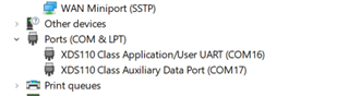
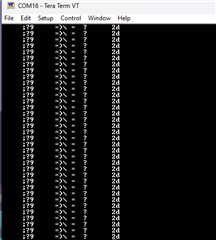
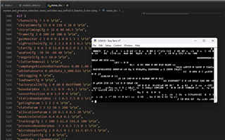
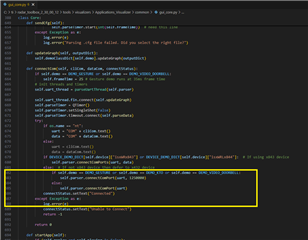
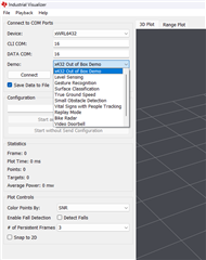
In Visualizer tool we need to send CLI configration file to the IWRL6432 device via UART (xds1100 emulator here). After that IWRL6432 device will send TLV data to the visualizer app via UART. This is my understanding of how the SDK demo works here.

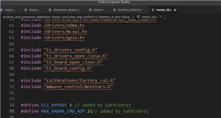
But i want to develop a custom code, 

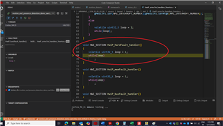
1. Board initialization,

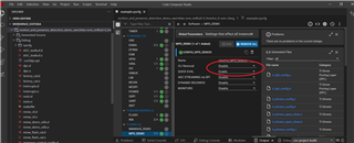
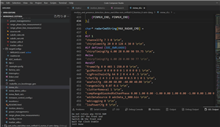
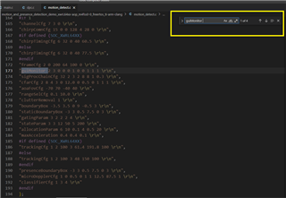
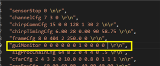
2. CLI hard coded data initialization,

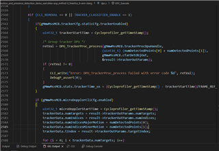
3. Function that gets the ADC data, function to process the ADC data to Digital front end data, function to identify human, function to find the distance of human,

4. Based on the output of the function, i could send the data to another host MCU via UART.

Could you tell me how to do the above things. I dont want to use the Visualizer / any other python code to transfer the CLI command. The program has to start with the CLI data i written in the CLI variable.

I am doing hard work to edit the demo code to make it work as per my custom requirement. Hope you would help me.

  • Hello, 

    Sorry for the delayed response. I think your best course of action would be to modify the existing SDK demo to meet your custom requirements. It is not too difficult to modify the demo to "hard code" the CLI configuration so you can start with that. 

    The easiest way to do hardcoded configuration (HCC) with xWRL6432 is using the QUICK_EVAL feature. To enable HCC, you can enable the QUICK EVAL setting in sysconfig for the example project. Note, the CLI_REMOVAL feature in sysconfig will not work for your case as it also removes the tracking and human classification layers so stick with QUICK_EVAL. Then in mmw_cli.c, you can list each of the configuration commands in radarCmdString (or radarCmdStringAOP if AOP device is used). Note, you may need to update MAX_RADAR_CMD to match the number of commands in your configuration. After this you can rebuild the example project and reflash the board with the updated appimage. If your configuration is valid then the sensor will begin chirping and outputting data once it receives power without the need to configure over UART.

    The SDK demo already includes the processing to track and classify a human so all you should need to do from there is add some code to calculate the range for tracked objects which are labeled as human, this should be easily done since the x, y and z coordinates are available for each tracked object. I believe all of the data you need for that processing should be available after the udoproc dpu runs in dpc_execute (dpc.c) so you can add in that additional logic there.

    Best Regards,

    Josh


  • Hi Josh, I selected the Quick Eval = enable;

    and also seen the radarCmdString, 


    After compiling, the processor hangs at  

    void HWI_SECTION HwiP_hardFault_handler()


    But i when do blink LED, with the example code, it blinks the user_LED, and also prints the UART COM16

    I want to know the continuation of program i.e. which function calling which function, what are all their initialization.
    So, I am planning to duplicate the blink LED code, without RTOS. Copy one by one function from the motion and presence detection demo and see what all functions are doing. In CLI initialization it should be HCC. Will my plan work out. or any other approach would you suggest? 

  • Hi,

    Did you change the MAX_RADAR_CMD as Josh said? This could cause a crash if you do not change it to the right amount of lines.

    Best,

    Nate

  • Hi Nate,

    In the Josh statement
    in mmw_cli.c, you can list each of the configuration commands in radarCmdString (or radarCmdStringAOP if AOP device is used). Note, you may need to update MAX_RADAR_CMD to match the number of commands in your configuration. After this you can rebuild the example project and reflash the board with the updated appimage.

    I dont understand match the number of commands in the configuration. So I could not try that step.

    So, To better undestand the flow of SDK, I imported mmwave_example code.

    In that code the program hangs at the function,  MMWave_init (&initCfg, &errCode); code executes and upto this line, after touching this 

    MMWave_initLink( ) , code hangs and goes to the HwiP_hardFault_handler().


  • Hello, 

    Sorry for they delayed response here. Is the issue resolved or you're still looking for assistance?

    I dont understand match the number of commands in the configuration

    It just means after adding all the configuration commands that you wish to hard code to radarCmdString, count the commands in radarCmdString and update the MAX_RADAR_CMD variable if needed to be greater than or equal to the total number of commands.

    Best regards,

    Josh

  • Hi Josh, After adding the lines below


    i could see in the terminal,


    here the configuration are hardcoded but, i cant read the output in the terminal.

    I want to get the information like how many humans are detected, co-ordinates(x,y,z) of humans. 

    how to display that detected information in the UART terminal??
    I use DebugP_logInfo ("No. of humans detected==\n");


    could you help me on this.


  • Hello, 

    I'm not sure if the hardcoded configuration is executing as expected in your test. You should not need to add CLI_BYPASS. And I can also see that you have modified MAX_RADAR_CMD_AOP, since you are not using an AOP device you should be modifying MAX_RADAR_CMD instead. Here are the full steps I have taken with the latest SDK (5.5.3.0) to implement HCC with a tracking configuration. 

    1. Import the motion and presence detection example project from C:\ti\MMWAVE_L_SDK_05_05_03_00\examples\mmw_demo\motion_and_presence_detection\xwrL64xx-evm to CCS

    2. Set QUICK EVAL to Enable in the MPD_DEMO tab of example.syscfg. Save the file.

    3. Open mmw_cli.c from the project explorer window and replace radarCmdString char array with below. Save the file.

    char* radarCmdString[MAX_RADAR_CMD] =
    {
    #if 1
    "channelCfg 7 3 0 \r\n",
    "chirpComnCfg 15 0 0 128 4 28 0 \r\n",
    "chirpTimingCfg 6 32 0 40 60.5 \r\n",
    "frameCfg 2 0 200 64 100 0 \r\n",
    "guiMonitor 2 3 0 0 0 1 0 0 1 1 1 \r\n",
    "sigProcChainCfg 32 2 3 2 8 8 1 0.3 \r\n",
    "cfarCfg 2 8 4 3 0 12.0 0 0.5 0 1 1 1 \r\n",
    "aoaFovCfg -70 70 -40 40 \r\n",
    "rangeSelCfg 0.1 10.0 \r\n",
    "clutterRemoval 1 \r\n",
    "compRangeBiasAndRxChanPhase 0.00 1.00 0.00 -1.00 0.00 1.00 0.00 -1.00 0.00 1.00 0.00 -1.00 0.00 \r\n",
    "adcDataSource 0 adcData_1_000.bin \r\n",
    "adcLogging 0 \r\n",
    "lowPowerCfg 0 \r\n",
    "factoryCalibCfg 1 0 40 0 0x1ff000 \r\n",
    "boundaryBox -3.5 3.5 0 9 -0.5 3 \r\n",
    "sensorPosition 0 0 1.9 0 0 \r\n",
    "staticBoundaryBox -3 3 0.5 7.5 0 3 \r\n",
    "gatingParam 3 2 2 2 4 \r\n",
    "stateParam 3 3 12 50 5 200 \r\n",
    "allocationParam 6 10 0.1 4 0.5 20 \r\n",
    "maxAcceleration 0.4 0.4 0.1 \r\n",
    "trackingCfg 1 2 100 3 61.4 191.8 100 \r\n",
    "presenceBoundaryBox -3 3 0.5 7.5 0 3 \r\n",
    "microDopplerCfg 1 0 0.5 0 1 1 12.5 87.5 1 \r\n",
    "classifierCfg 1 3 4 \r\n",
    "baudRate 1250000 \r\n",
    "sensorStart 0 0 0 0 \r\n"
    #endif
    };

    4. Open mmw_cli.h from C:\ti\MMWAVE_L_SDK_05_05_03_00\examples\mmw_demo\motion_and_presence_detection\source\ and change MAX_RADAR_CMD to 28. Save the file.

    5. Build the project in CCS and flash the generated .appimage file

    Then after you connect to the device in a serial terminal with the same baud rate as in the baudrate command of the configuration (1250000 in the configuration above) you should see the stream of UART data. 

    i cant read the output in the terminal.

    Our examples output relevant data over UART in the format described here. The raw UART data seen in the terminal will not be readable. The data should be parsed by the host MCU before any additional processing. We do this same parsing of the data when its received by the PC before plotting it in a visualizer/GUI. 

    how to display that detected information in the UART terminal??

    You can use the CLI_write function if you wish to print in the terminal but I don't recommend this as it will probably be too slow. If you want to visualize the data to confirm everything works to your liking before connecting to a host MCU you can use our open source python visualizer (mmWave Industrial Visualizer from the Radar Toolbox).

    Note, you will need to make one small change in the visualizer source code to accommodate the hard coded configuration. Line 685 of gui_core.py (RTB 2.30.00.12) should be changed to "self.parser.connectComPort(uart, 1250000)". After this change the Connect without send configuration button in the GUI will start parsing and visualizing the data. 

    Best regards,

    Josh

  • Hi Josh,
    Thanks for the detailed steps. Actually, I am using IWRL6432AOP EVM. So only changed the MAX_RADAR_CMD_AOP configuration. 

    Once Built with given Hardcode configuration file, i am getting data in the UART in very speed plotting in non-readable format.


    In the Industrial visualizer source code, it is already set with baud rate (uart1250000)".
      

    But in Industrial Visualizer, which demo need to select? actually i tried all with by selecting start without send configuration


    But I dont see any plots there. It is simply same as before. But when i open in the UART terminal data is continuously plotting(by this time i closed industrial visualiser and vise versa).


    Moreover I dont want too see the data in any visualizer.

    I want to get only all processed and logically coded data in the UART as readable format.

    I need to do the following things in the motion and presence detection demo code

    1. Hardcoded the configuration file based on the set value of boundary and number of persons---> (Now I am able to hardcode the cfg data)

    2. I want to create a logical coding inside the dpc file/any other, i.e after chirping i need to know how many humans detected and his coordinates.
    3. If glass wall is detected? If yes , then human present inside/outside the wall
    4. For debugging purpose, i need to see the human presence data in the UART terminal as readable/editable.
    5. once this data finalized in this chip itsef, i will only send the required data to another MCU via UART/SPI/GPIO. 

    For the above five steps, I need the solution.

  • Hello, 

    Okay. I understand that you don't want to see the data in the visualizer. Just to clarify my point. If you refer to my previous post I mentioned "Line 685 of gui_core.py (RTB 2.30.00.12) should be changed to "self.parser.connectComPort(uart1250000)""

    In the Industrial visualizer source code, it is already set with baud rate (uart1250000)".

    This is not correct. You need to make line 685 the same as line 683 in the picture you sent. Then the start without send configuration will work. And to answer your question for the motion and presence detection demo you should select x432 Out of Box Demo.

    2. I want to create a logical coding inside the dpc file/any other, i.e after chirping i need to know how many humans detected and his coordinates.

    This information is available in the DPC_Execute() function in dpc.c. After the call to DPU_TrackerProc_process the tracked targets and their coordinates are stored in &result->trackerOutParams. 

    3. If glass wall is detected? If yes , then human present inside/outside the wall

    This isn't something that the demo currently does so you may need to implement your own algorithm here. Clutter removal is enabled by default in the configuration but if you disable it you may be able to detect a static wall and if you the person is being tracked then you will know their coordinates so you can check against the walls position. 

    4. For debugging purpose, i need to see the human presence data in the UART terminal as readable/editable.

    As I mentioned in my previous post, CLI_write() function can be used to print this data in a readable format in the UART terminal. You will also want to change the guiMonitor configuration command to all 0 to disable the normal data output so that you can read the values you are printing. 

    regards,

    Josh

  • Hi Josh,
    Thanks for responding so fast, you saved my day.

    Josh Said
    1.  the tracked targets and their coordinates are stored in &result->trackerOutParams.,


    In this code, where should (line number) I place the  CLI_write() to get the tracked target and their coordinates, could you give me full syntax/code to print the data in UART. Actually when flashed, this code continuously printing data to the UART(non-readable format).  So first we should stop that default printing for visualizer and then we have to start print our required data. How to do that? 

    Josh Said
    2.  The demo currently does so you may need to implement your own algorithm here.,

    Later i come to this topic, since first i want to explore the data which is sent by the 6432AOP.

    Josh Said
    3.  You will also want to change the guiMonitor configuration command to all 0 to disable the normal data output so that you can read the values you are printing. 

    guiMonitor present is four places in the motion_detect.c file, which one need to be changed, (FYI, it is all in disabled state). I changed all all four to zero.

    [guiMonitor 0 0 0 0 0 0 0 0 0 0 0],

    after this step also, I am getting data in UART as non-readable only.

    4. In this link Human Non-human Classification User Guide
    Visualizer marks human, Is it the algorithm done in python/within HWA of chip?

    I do want to print in UART human is present at coordinates, just like given in the link  

     
  • Hello, 

    In this code, where should (line number) I place the  CLI_write() to get the tracked target and their coordinates, could you give me full syntax/code to print the data in UART.

    Providing custom modifications to the demo code is outside the scope of these forums.

    Actually when flashed, this code continuously printing data to the UART(non-readable format).  So first we should stop that default printing for visualizer and then we have to start print our required data. How to do that? 

    This would indicate that the guiMonitor command in the configuration still enables some outputs. 

    guiMonitor present is four places in the motion_detect.c file, which one need to be changed,

    radarCmdStringAOP is the character array that you need to modify. It is located in mmw_cli.c not motion_detect.c.

    Is it the algorithm done in python/within HWA of chip?

    The algorithm runs on the chip. The python code only handles the visualization of the data. 

    I do want to print in UART human is present at coordinates, just like given in the link  

    In that case, along with the tracked target position information available in &result->trackerOutParams, the tracked target classification information is available after the micro-doppler dpu runs (DPU_uDopProc_process) in &result->microDopplerOutParams. So you should be able to add your code to the end of the DPC execute function, at that point all of the processing for a given frame is completed and the data you need is available.

    Best regards,

    Josh

  • Thanks Josh,

    Now I do have the understanding of the demo. 

    Question 1: Regarding discarding a digit in guiMonitor
    I played with guimonitor, giving 1 at various position.

    I am getting data from 

    mmwDemo_TransmitProcessedOutputTask() at motion_detect.c

    But I have doubt, in the sdk document guiMonitor has 12 digits/position

    But in all chirp_configs files given in examples has 11 digits only. How? Which one digit need to discard?


    Question 2: Variable name converted as integers to print UART

    In the dpc.c file at the end the  DPC_Execute(), function i would add the CLI_write("%d, ", required data);

    I want required data to be filled as integer. But In the demo code the variables are declared as global structures, structures, pointers. So I don't know how to get the data from result->trackerOutParams and result->microDopplerOutParams as integers to print in  CLI_write().

    Required data as integers are

    1. Motion detected is Human or not

    2. Detected human present in which zone

    3. Detected human location in x,y position

    4. Mico Doppler data, showing minor human motion is detected at which zone.

    Most important is i need in ceiling mount.

    Kindly give me the variable names converted as integers.

  • Hello, 

    But in all chirp_configs files given in examples has 11 digits only. How? Which one digit need to discard?

    The 12th position is optional and was added in a later update so many default configurations do not have it. I'm not sure what you mean by "which one digit". If you want to disable the normal UART demo output then all positions for guiMonitor should be 0.

    I want required data to be filled as integer. But In the demo code the variables are declared as global structures, structures, pointers. So I don't know how to get the data from result->trackerOutParams and result->microDopplerOutParams as integers to print in  CLI_write().

    At the end of dpc_execute you could iterate through each of the tracked targets with something like a for loop. There is a numTargets variable in result->trackerOutParams that could be used for this. You will need to dereference the pointers/cast the data to the appropriate type. 

    Regards,

    Josh

  • Hello Josh,

    As I mentioned earlier, I need Ceiling Mount. If I tried to capture the human location data. I need to enable the human/non-human classifier and also i need minor motion of human.

    "sensorPosition 0 0 2.5 0 90 \n \r",

    "minorStateCfg 5 4 40 2 1 40 8 20 \n \r",

    "clusterCfg 1 0.5 2 \n \r",

    "gatingParam 3 2 2 2 4 \n\r",

    "stateParam 3 3 12 50 5 200 \n\r",

    "allocationParam 6 10 0.1 4 0.5 20 \n\r",

    "maxAcceleration 0.4 0.4 0.1 \n\r",

    "trackingCfg 1 2 100 5 61.3 191.7 100 \n\r",

    "presenceBoundaryBox -2 2 -2 2 0 2  \n\r",

    "microDopplerCfg 1 0 0.5 0 1 1 12.5 87.5 1 \n\r",

    "classifierCfg 1 3 4 \n\r",

    I get the error throwed, code is not executing. In the tuning guide it is mentioned that we cant use both trackingCfg and minorStateCfg at the same time.

    If only Minor motion is enabled, in ceiling mount, sensor is picking up the small curtain movement also as human minor motion. So, If I get minor motion along with whether it is a Human or Non-Human, this will solve the problem. But I can't enable both!!! How to solve this?

  • Hello, 

    Could you please create a new thread for this topic. As the rest of this thread is mostly related to hardcoding the configuration and outputting data to CLI. It will improve findability for others who are searching for help on the same topic. 

    Best regards,

    Josh