Tool/software:
Hi,
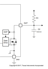
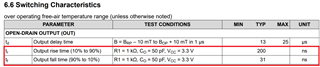
Could you tell us how the switching characteristics on the datasheet vary between TR (Output rise time) and TF (Output fall time)?
BR,
Taku Murayama
Tool/software:
Hi,
Could you tell us how the switching characteristics on the datasheet vary between TR (Output rise time) and TF (Output fall time)?
BR,
Taku Murayama