Tool/software:
Hi Team,
I am trying to program AWRL1432-boost with XDS100 debug probe in which signals are taken from 60pin DCA connector associated resistor, connection.
resistor -> R,
R40 - TMS ---> xds TMS
R37 - TDI ---> xds TDI
R132 - VCC ----> xds vcc
R34 - TDO -----> xds TDO
R38 - TCK ------> xds TCK
R63 - NRST -----> xds TRST
and switch setting.
S1
1 - SOPC - ON all other's switch's are in off state.
S2
1 - DCA JTAG
3 - CAN_EN
4 - LIN_EN
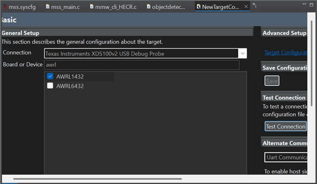
ccs - ccxml setting
when I give test connection, I'm unable to test full data where it gives out clk error mentioned below.
[Start: Texas Instruments XDS100v2 USB Debug Probe_0]
Execute the command:
%ccs_base%/common/uscif/dbgjtag -f %boarddatafile% -rv -o -F inform,logfile=yes -S pathlength -S integrity
[Result]
-----[Print the board config pathname(s)]------------------------------------
C:\Users\ESWARA~1\AppData\Local\TEXASI~1\
CCS\ccs1220\0\0\BrdDat\testBoard.dat
-----[Print the reset-command software log-file]-----------------------------
This utility has selected a 100/110/510 class product.
This utility will load the adapter 'jioserdesusb.dll'.
The library build date was 'Sep 26 2024'.
The library build time was '10:09:41'.
The library package version is '20.0.0.3178'.
The library component version is '35.35.0.0'.
The controller does not use a programmable FPGA.
The controller has a version number of '4' (0x00000004).
The controller has an insertion length of '0' (0x00000000).
This utility will attempt to reset the controller.
This utility has successfully reset the controller.
-----[Print the reset-command hardware log-file]-----------------------------
The scan-path will be reset by toggling the JTAG TRST signal.
The controller is the FTDI FT2232 with USB interface.
The link from controller to target is direct (without cable).
The software is configured for FTDI FT2232 features.
The controller cannot monitor the value on the EMU[0] pin.
The controller cannot monitor the value on the EMU[1] pin.
The controller cannot control the timing on output pins.
The controller cannot control the timing on input pins.
The scan-path link-delay has been set to exactly '0' (0x0000).
-----[The log-file for the JTAG TCLK output generated from the PLL]----------
There is no hardware for programming the JTAG TCLK frequency.
-----[Measure the source and frequency of the final JTAG TCLKR input]--------
There is no hardware for measuring the JTAG TCLK frequency.
-----[Perform the standard path-length test on the JTAG IR and DR]-----------
This path-length test uses blocks of 64 32-bit words.
The JTAG IR instruction path-length was not recorded.
-----[Perform the Integrity scan-test on the JTAG IR]------------------------
This test will use blocks of 64 32-bit words.
This test will be applied just once.
Do a test using 0xFFFFFFFF.
Scan tests: 1, skipped: 0, failed: 0
-----[An error has occurred and this utility has aborted]--------------------
This error is generated by TI's USCIF driver or utilities.
The value is '-183' (0xffffff49).
The title is 'SC_ERR_CTL_CBL_BREAK_FAR'.
The explanation is:
The controller has detected a cable break far-from itself.
The user must connect the cable/pod to the target.
[End: Texas Instruments XDS100v2 USB Debug Probe_0]
Can you instruct a way to solve this and use JTAG for programming.
Also during debugging TDI and TCLK is 0.001V close to zero only in flash mode it's working
Regards,
Eswaramoorthy Sugavanam


