This thread has been locked.

If you have a related question, please click the "Ask a related question" button in the top right corner. The newly created question will be automatically linked to this question.

IWR6843ISK: IWR6843 EVM boot and UART communication issue

Part Number: IWR6843ISK
Other Parts Discussed in Thread: IWR6843

Tool/software:

Setup:

IWR6843ISK EVM with Mainboard, Mainboard contains FTDI chip for UART to USB, Laptop connected with this board to view UART logs. IWR6843ISK mated with mainboard using 60-pin B2B connector, DC adapter used to power both boards ie. B2B used to deliver power from mainboard to IWR643ISK

Issue:

Initially, UART communication was not working upon powering on the supply, unless the IWR6843ISK was power cycled. Probed the entire UART path, from FTDI to IWR6843 UART pins to realize that the FTDI was working fine, whatever was typed on the console was getting converted to its UART packet. The only way to resolve the issue was to power cycle the IWR6843ISK board with the UART pins connected to mainboard. Power cycle of IWR6843ISK without UART connected to powered mainboard does not resolve the issue

Observation:

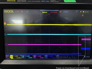
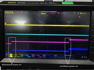
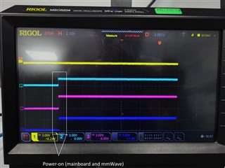
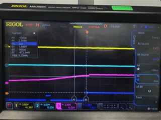
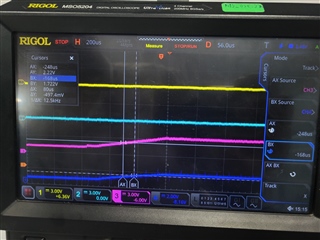
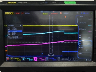
When UART TX and RX of IWR6843ISK are connected to mainboard, nRESET remains high due to the pullup on the mainboard UART side and this back-supplying the 3V3 rail on the IWR6843ISK to which the nRESET is also pulled up. First time power ON of both boards results in UART not working. During this condition, if we powercycle only the IWR6843ISK board (ie., UART connected to mainboard thereby nRESET in High state, and VIOIN turned OFF then ON), it resolves the issue. IWR6843 reads from the QSPI flash and UART logs can be observed. However, if we remove the UART connections (nRESET brought down to low) then power cycle the IWR6843ISK, UART does not work and there are no transactions on the QSPI lines. In short, IWR6843 works only when nRESET is de-asserted THEN VIO is supplied. This was verified by adding a load switch delay to the 5V supply. This time, the nRESET is pulled high earlier through the UART pins back-supplying the 3V3 rail on the IWR6843ISK, post which the 5V rises (thanks to the delay caused by load switch with an RC delay on its EN) and the VIO is supplied to the IWR6843.In this case, the IWR6843ISK works on first time power on itself.

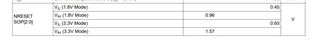
This is contradictory to the clause mentioned on the IWR6843 datasheet, that nRESET must be deasserted only after the power rails have reached their stable state - it works only when its the other way round, when nRESET is deasserted and in HIGH state before VIO reaches its level. We also tried manually asserting the nRESET using the S2 switch on the board, while the board was in working state and UART logs were obsevable, and we found that the UART locked up again.

  • Hi Barath,

    Please allow us couple of days to check this issue.

    Regards

    Ankit

  • Hi Barath,

    Could you please elaborate on how UART connection is related to NRESET assertion? UART connection to mainboard should not impact NRESET being High or Low as these are two independent instances.

    Also, I would like to know if mmWave board is always connected to Main board during power up? This could cause booting failure as the interfaces would be pulled up or driven by external HOST without VIO being present. 

    IWR6843ISK mated with mainboard using 60-pin B2B connector, DC adapter used to power both boards ie. B2B used to deliver power from mainboard to IWR643ISK

    Does this mean that the ISK board is being powered up through the main board using B2B connector? Could you please try booting up both independently then connect both and perform a NRESET to see if the issue is resolved?

    Regards

    Ankit

  • Could you please elaborate on how UART connection is related to NRESET assertion? UART connection to mainboard should not impact NRESET being High or Low as these are two independent instances.

    When the UART lines are conencted, nRESET is at 1.7V as per our probing, even when the TI board is not powered ON through the 5V. I suspect this is due to the UART being pulled-up on the mainboard and this somehow reverse supplying the 3V3 rail on the TI board

    Also, I would like to know if mmWave board is always connected to Main board during power up? This could cause booting failure as the interfaces would be pulled up or driven by external HOST without VIO being present.

    We tried isolating the UART and all other connections, purely powering on both boards separately and connecting the UART post that. Still we are not getting logs unless we power-cycle the TI board with this UART connected. Power cycling without the UART doesn't help, no UART then. 

    Does this mean that the ISK board is being powered up through the main board using B2B connector? Could you please try booting up both independently then connect both and perform a NRESET to see if the issue is resolved?

    We tried the same. I took out wires from the mainboard for the UART, powered both boards from different sources and connected uART yet it doesn't solve the issue. Powered from different sources and tied the GND of both boards and still there's no improvement. Only way to make it work is by having the UART connected (thereby nRESET at HIGH) then power-cycling the TI board. 

  • We tried isolating the UART and all other connections, purely powering on both boards separately and connecting the UART post that. Still we are not getting logs unless we power-cycle the TI board with this UART connected. Power cycling without the UART doesn't help, no UART then.

    Did you perform a NRESET after connecting both the boards? It is recommended to perform NRESET after every connection for ensuring correct booting up of the device.

    When the UART lines are conencted, nRESET is at 1.7V as per our probing, even when the TI board is not powered ON through the 5V. I suspect this is due to the UART being pulled-up on the mainboard and this somehow reverse supplying the 3V3 rail on the TI board

    This should not be the ideal case. NRESET and UART are two independent instances and should not be affected due to UART being pulled up. Could you please connect both the boards keeping main board powered off --> power the radar board --> perform NRESET --> power on the main board --> power on the radar board. The above steps would resolve the issue.

    Also, to determine if this is a device boot up related issue or UART issue. Could you please measure the VBGAP voltage after connecting to main board. 

    Regards
    Ankit

  • Did you perform a NRESET after connecting both the boards? It is recommended to perform NRESET after every connection for ensuring correct booting up of the device.

    Yes, we did the nRESET and that didn't solve the issue. Infact, when in working condition, pressing and releasing the nRESET puts the board back to the non working UART locked up state. 

    This should not be the ideal case. NRESET and UART are two independent instances and should not be affected due to UART being pulled up. Could you please connect both the boards keeping main board powered off --> power the radar board --> perform NRESET --> power on the main board --> power on the radar board. The above steps would resolve the issue.

    We tried the same and still couldn't get it to work

    However, one thing that does seem to work is toggling S1.1 on the mmWave board to the ON state. When that is done, the UART logs are obtained right at the first boot and nRESET assertion and deassertion using the button also yields the respective logs and the board rebooting with proper UART logs. In short, S1.1 on the ON state gets the job done and the board works as expected. But this is in contrast with the user guide that states that S1.1 on the ON position puts the board on flashing mode while the same on OFF position makes it boot into functional mode. I also believe that the UART locking up all throughout was not due to the board not booting up, but due to it entering the flashing mode. In short, the S1.1 switch is behaving the opposite way as to what is mentioned in the user guide in our case.

  • Hi Bharath,

    Could you please capture the VBGAP voltage. As well as the SOP 2.1.0 waveforms along with NRESET at the time of reset release to check if the SOP registration is happening correctly.

    Or you can read the below register to check the SOP mode through JTAG connection using CCS software tool.

    SOP mode register: FFFF E268 (Flash mode should read 0x00000005, Functional Mode should read 0x00000001)

    Regards

    Ankit

  • Could you please capture the VBGAP voltage. As well as the SOP 2.1.0 waveforms along with NRESET at the time of reset release to check if the SOP registration is happening correctly.

    Thank you for the prompt response. We haven't gotten the time to check the SOP waveforms or JTAG as of yet but we did check the VBGAP voltage and it was at 0.884V, regardless of what state the board was in (Functional, flashing etc.). Also, while connecting the mmWave board as standalone (without mating it to any carrier board) and toggling the 5th position of the switch S1 to switch UART to the Micro USB port on the board, we are observing the same behaviour. If the S1.1 is at OFF, board goes into flashing mode and toggling it to ON would work and we'd see the UART logs.

  • Hi Bharath,

    Thank you for confirming VBGAP coming up means device is waking up. But oscilloscope capture or memory register reading would have enabled us with SOP mode information. Seems this issue is with Flashing mode. I will check this internally more, while you confirm the SOP mode registration during NRESET release.

    Regards

    Ankit

  • Hi Bharath,

    Are you seeing this across all EVMs?

    Regards

    Ankit

  • Hi Ankit,

    I have tested using two mmWave boards so far, both of them exhibit this behaviour.

    Below are the captures of SOP0,1,2 and nReset. 

    SOP2 is in Yellow, Probed at R203 towards the sensor

    SOP1 is in Light Blue, probed at R206 towards the sensor

    SOP0 is in Pink, probed at R209 towards the sensor

    nRESET is in Dark blue, probed at the output of the AND gate and towards the sensor

    Case 1: Both boards powered at the same time

    In this case, 5V is supplied to the mainboard using a DC adapter, and the same also powers the mmWave board through the B2B connector. UART does not show in this case and board (seemingly) boots into flashing mode. Configuration of S1 in this case (from 1 to 6): 001100

    Case 2: Mainboard powered first then mmWave board is powered

    In this case, 5V is supplied first to the mainboard through the DC jack, and after a delay the mmWave board is powered. The board does boot into functional mode and we are seeing the UART logs. However, one important observation here is that the nRESET and SOP pins pulled up to 3V3 do not rise from proper 0V and instead, it seems to rise up from some kind of floating state that is offset positively from 0. This is not observed when we isolate the UART pins, in which case nRESET rises from proper 0 and board goes into flashing mode. Configuration of S1 in this case (from 1 to 6): 001100

    Case 3: Both boards powered at the same time but S1.2 set to ON

    Same as case 1 but the S1.2 is set to ON. This is SOP mode 1 from my understanding and as per the software team, this mode is not configured. The board does boot into functional mode and we are seeing the UART logs. Configuration of S1 in this case (from 1 to 6): 011100

  • Hi Bharath,

    Thank you for the oscilloscope captures but we would need the time scale in milliseconds to see the exact NRESET release.

    However, please find my observations below.

    SOP configurations:

    Case 1:

    SOP2 - 0, SOP1 - 0, SOP0 - 0 (At the time of reset release). Hence, undefined SOP mode.

    Case 3:

    SOP2 - 0, SOP1 - 0, SOP0 - 1 (At the time of reset release the SOP0 is higher than VIH level of 1.57V during first step). Hence, Functional SOP mode.

    Case 3:

    SOP2 - 0, SOP1 - 1, SOP0 - 1 (At the time of reset release). Hence, device boots up in DEV/DEBUG mode and the RS232 is accessible.

    We will have more clear idea once we have scope shot in millisecond scale and please place a cursor at 1.57V for NRSET signal.  Also, is this behaviour only for single EVM or across EVMs?

    Regards

    Ankit

  • Hi Ankit,

    I have re-captured the waveforms by adjusting the time scale. For the nRESET, I have placed the cursors at around 1.5V and for the SOP signals, as per the datasheet the Vih mentioned was 2.25V so I've approximately placed the cursors there.

    Case 1:

    SOP0 seems to rise 160us before nRESET

    Case 2:

    in this case, its similar although the signals seem to be rising from a non-zero state (initial power-on of the carrier board was done earlier and hence the rise from 0 was not captured in this frame). 

    Case 3:

    I have captured the delay betwen SOP0 and SOP1 rising, since we already have the SOP0 vs. nRESET delay.

    Also, is this behaviour only for single EVM or across EVMs?

    We have tested with two EVMs and both exhibit this behaviour

  • Hi Bharath,

    The VIH for NRESET and SOP signals is 1.57V, please see below.

    It looks like a NRESET release is happening for shorter period (above VIH) before proper release in the below shown image booting up the device in undefined SOP MODE: 000. Can you check this on another EVM apart from 2?

    Regards

    Ankit