This thread has been locked.

If you have a related question, please click the "Ask a related question" button in the top right corner. The newly created question will be automatically linked to this question.

TUSS4470: Issue with TUSS4470 Vout Signal and Echo Detection

Part Number: TUSS4470

Tool/software:

Hello everyone,

I am currently working on a project using the STMF4 series to drive the TUSS4470, paired with a 1 MHz transducer. I aim to capture echo signals, but I’ve encountered some issues with the Vout output when observed on an oscilloscope.

I conducted two experiments:

  1. Placing the transducer at the bottom of a cup to measure water height, as per the application manual.
  2. Positioning the transducer approximately 25 cm away from a wall.

In both cases, I noticed the following behavior:

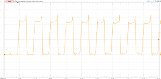
  • Even without transmitting a pulse, the Vout pin of the TUSS4470 outputs a stable, periodic pulse. Is this noise?
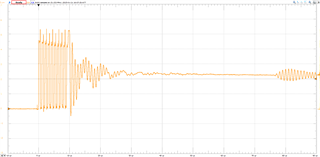
  • After transmitting a pulse, the Vout pin only shows the transmitted pulses, with no apparent echo signal. As shown in this photo, no pulses are emitted before the oscilloscope is triggered.These two pictures are the same as the previous one, but zoomed in to 1ms and 100us.
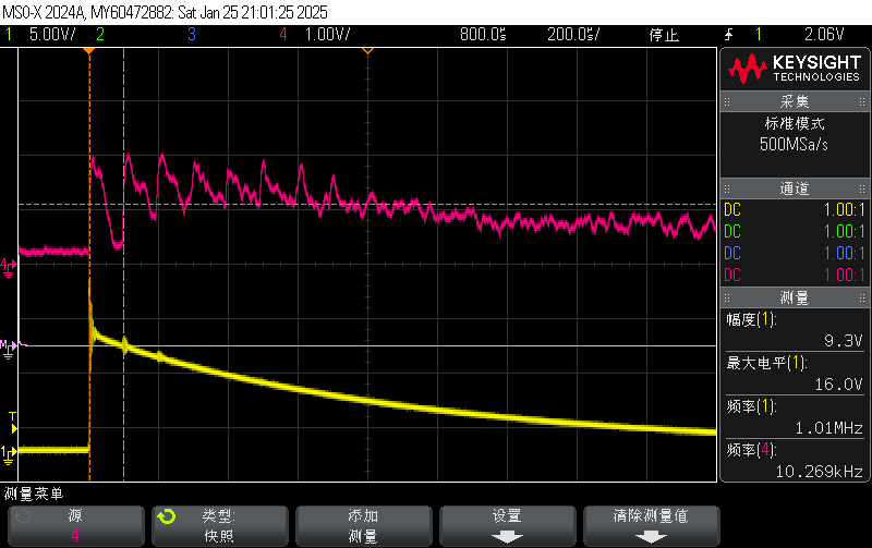
  • To supplement the image, the blue line is the Vout pin and the yellow line is the positive pole of the emitter.

How can I confirm whether the echo signal is being received correctly? Could this behavior be related to my setup or configuration?

Any guidance or suggestions to debug this issue would be greatly appreciated!

Thanks in advance!

  • This is my chip setup.

        TUSS4470_Write_Register(BPF_CONFIG_1, 0x5F, &write_back[0]);
        HAL_Delay(1);
        TUSS4470_Write_Register(BPF_CONFIG_2, 0x00, &write_back[1]);
        HAL_Delay(1);
        TUSS4470_Write_Register(DEV_CTRL_1, 0xB7, &write_back[2]);
        HAL_Delay(1);
        TUSS4470_Write_Register(DEV_CTRL_2, 0xC0, &write_back[3]);
        HAL_Delay(1);
        TUSS4470_Write_Register(DEV_CTRL_3, 0x00, &write_back[4]);
        HAL_Delay(1);
        TUSS4470_Write_Register(VDRV_CTRL, 0x5F, &write_back[5]);
        HAL_Delay(1);
        TUSS4470_Write_Register(ECHO_INT_CONFIG, 0x00, &write_back[6]);
        HAL_Delay(1);
        TUSS4470_Write_Register(ZC_CONFIG, 0x00, &write_back[7]);
        HAL_Delay(1);
        TUSS4470_Write_Register(BURST_PULSE, 0x04, &write_back[8]);
        HAL_Delay(1);
        TUSS4470_Write_Register(TOF_CONFIG, 0x00, &write_back[9]);
        HAL_Delay(1);

  • I can provide any information, hardware or code you need.

  • To supplement the image, the blue line is the Vout pin, and the yellow line is the positive pole of the transmitter. In addition, I would like to know whether the transmitting waveform is normal, and why the last waveform is different from the previous ones?

  • Hello Junhao,

    Thanks for posting to the sensors forum. It definitely looks like you could be seeing some noise in your signal path somehow. The reason I believe it is noise is because it looks very cyclical (approximately every 40us). You may need to track down what could be causing this noise to ensure that it doesnt show up in your output. 

    As far as the image provided on the transducer being driven, this waveform does not look quite right. The main issues with it is that it seems like the voltage swing doesn't look appropriate and the frequency also doesn't look like it is switching at 1MHz but again image is too far to be able to see the frequency clearly.

    Here is a capture of what it looks like on my end.

    How did you attach the transducer to the cup?

    Best,

    Isaac

  • Hello Isaac,

    Thank you for your guidance! As shown in the attached image, I have successfully driven the chip and achieved the desired results in my experiment to measure the liquid level in the cup. However, this is only visible on the oscilloscope.

    In practice, I aim to use this chip and the 1MHz transducer to achieve the smallest and most precise sensing range possible. I would like to ask if you have any additional tips to help me accomplish this. For example, I know that adding a damping resistor can reduce the transducer's oscillation time. Are there any other techniques I should consider?

    Additionally, could you advise me on the ideal ADC sampling rate for this application?

    Lastly, as shown in Figure 2, I noticed the statement in the datasheet:
    "The distances shown in the legend were computed in post-processing."

    Could you clarify what specific post-processing operations are involved? Is there any example code available for this? The provided example project only demonstrates ADC data acquisition. How can I process the data to generate smooth waveforms like those shown in the datasheet?

    Thank you again for your support!

    Best regards,
    Junhao

  • Hello Junhao,

    I am glad to hear you were able to get this working. In order to get the smallest sensing range possible you would need to use what is considered a bistatic configuration. This uses two transducers one of them is used for the transmit signal while the second is used to receive the signal. This essentially would remove the excitation from the RX side which is the biggest factor that determines minimum distances. 

    For a bistatic system you tend to need a separate device for the RX and a separate device for the TX along with two transducers, you can make a pseudo bistatic system with the TUSS4470 by using two transducers but you will still get some internal coupling from the TX side of the circuit but it wont be as what you are currently experiencing. 

    For a monostatic system that uses direct drive the damping resistor is a good option, but there isn't much else you can do for these types of systems.

    For the ADC sampling rate I would try to go for around 2MHz. You may not need to go as high since you are not looking at the individual waveforms since you are looking at the envelope of the signal. 

    The post processing that was performed on these images were all for the level detection, but we do not have an example code available for this. There is a small explanation on how this was performed on the app note if this is something that you are curious about. Other than that there was no additional processing beyond what the device provides/recommends. I believe these captures don't use two of the stages for the log amp which is how they are able to generate smooth waveforms as shown. You could add additional filtering to make them smoother though.

    Best,

    Isaac

  • Hi Isaac,

    Thank you for your detailed response. I have been experimenting with various signal processing algorithms over the past few days, but unfortunately, I still haven't been able to receive any echo signals from the air. At this point, I suspect the issue might be related to either the drive voltage or the acoustic impedance matching.

    Currently, I have VPWR internally connected to VDRV, but if I understand correctly, this limits VDRV to a maximum of 20V. To further increase the drive voltage, would it be possible to set VDRV_HI_Z high and directly connect VDRV to a (36-0.3)V power supply?

    Additionally, if I want to drive a 1MHz piezoelectric transducer with a higher voltage, what are my best options? I noticed that PRE_DRIVER_MODE is only supported for 400kHz operation. If I were to use Direct Transducer Drive MODE and connect an external FET for high-voltage driving instead of enabling PRE_DRIVER_MODE, what potential issues or limitations should I be aware of?

    Looking forward to your insights!

    Best,
    Junhao

  • Hello Junhao,

    Thanks for the update. That is correct VDRV can only go up to 20V but you have to ensure that VPWR has a higher voltage at all times to ensure that the device does not damage itself. So if you do use an external supply for VDRV you still have to ensure that the voltage on VPWR is higher than that off your VDRV supply.

    The best option to run a 1MHz would be to use the direct transducer drive mode as this is the only mode that reaches the 1MHz. What is the max distance you are trying to detect? I am not certain you would need to go that high on the voltage if the maximum sensing range is not that large.

    Best,

    Isaac