Other Parts Discussed in Thread: UNIFLASH, MMWAVEICBOOST, IWR6843, IWR6843ISK, IWR6843AOPEVM
Tool/software:
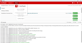
1. I have flashed binary from following path using uniflash (SPO0 and SPO2 In ON condition):
C:\Users\mmwave_industrial_toolbox_4_12_0\mmwave_industrial_toolbox_4_12_0\labs\People_Counting\3D_People_Counting\prebuilt_binaries\3D_people_count_68xx_demo.bin
Flashing is successful
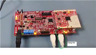
2. Now I have removed SOP2 jumper From MMWAVEICBOOST board.
3. Rebooted setup.
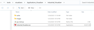
4. Opened Virtualizer from following path:
C:\Users\\mmwave_industrial_toolbox_4_12_0\mmwave_industrial_toolbox_4_12_0\tools\Visualizer\mmWave_Industrial_Visualizer.exe
5. Here selected following:
a. Demo : 3D people counting
b. Clicked in connect
c. Configuration :C:\Users\110813\Downloads\mmwave_industrial_toolbox_4_12_0\mmwave_industrial_toolbox_4_12_0\labs\People_Counting\3D_People_Counting\chirp_configs\ODS_6m_default.cfg
d. Clicked on Start and Send Configuration
Getting Following on console:
Python is 64 bit
Python version: sys.version_info(major=3, minor=6, micro=0, releaselevel='final', serial=0)
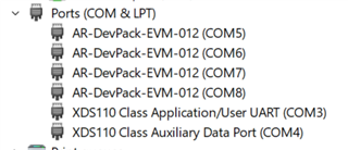
CLI COM Port found: COM3
Data COM Port found: COM4
Demo Changed to: 3D People Counting
{'startFreq': 60.75, 'numLoops': 64, 'numTx': 3, 'sensorHeight': 3.0, 'maxRange': 10, 'az_tilt': 0, 'elev_tilt': 0, 'idle': 30.0, 'adcStart': 25.0, 'rampEnd': 59.1, 'slope': 54.71, 'samples': 96.0, 'sampleRate': 2950.0}
Sensor Height from cfg = 2.0
Parser type: 3D People Counting
Connected
b'% SDK Parameters\n'
b''
b"% See the SDK user's gide for more informatin\n"
b''
b'% "C:\\ti\\mmwave_sdk_[VR]\\docs\\mmwave_sdk_use_guide.pdf"\n'
b''
b'sensorStop\n'
b''
b'flushCfg\n'
b''
b'dfeDataOutputMode 1\n'
b''
b'channelCfg 15 7 0\n'
b''
b'adcCfg 2 1\n'
b''
b'adcbufCfg -1 0 1 1 1\n'
b''
b'lowPower 0 0\n'
b''
b'\n'
b''
b'% Detection Layer Paraeters\n'
b''
b'% See the Detection Laer Tuning Guide for moe information\n'
b''
b'% "C:\\ti\\mmwave_industial_toolbox_[VER]\\labspeople_counting\\docs\\3_people_counting_detetion_layer_tuning_guid.pdf"\n'
b''
b'profileCfg 0 60.75 30.0 25.00 59.10 657930 054.71 1 96 2950.00 2 136 \n'
b''
b'chirpCfg 0 0 0 0 0 0 01\n'
b''
b'chirpCfg 1 1 0 0 0 0 02\n'
b''
b'chirpCfg 2 2 0 0 0 0 04\n'
b''
b'frameCfg 0 2 96 0 5500 1 0\n'
b''
b'dynamicRACfarCfg -1 4 2 2 8 12 4 12 5.00 8.0 0.40 1 1\n'
b''
b'staticRACfarCfg -1 6 22 2 8 8 6 4 8.00 15.000.30 0 0\n'
b''
b'dynamicRangeAngleCfg - 0.75 0.0010 1 0\n'
b''
b'dynamic2DAngleCfg -1 30 0.0300 1 0 1 0.30 0.5 8.00\n'
b''
b'staticRangeAngleCfg -10 8 8\n'
b''
b'antGeometry0 0 0 -1 -1-2 -2 -3 -3 -2 -2 -3 -\n'
b''
b'antGeometry1 0 -1 -1 00 -1 -1 0 -2 -3 -3 -2\n'
b''
b'antPhaseRot 1 -1 -1 1 -1 -1 1 1 -1 -1 1\n'
b''
b'fovCfg -1 70.0 70.0\n'
b''
b'compRangeBiasAndRxChanhase 0 1 0 1 0 1 0 1 01 0 1 0 1 0 1 0 1 0 1 1 0 1 0\n'
b''
b'\n'
b''
b'% Tracker Layer Parameers\n'
b''
b'% See the Tracking Layr Tuning Guide for mor information\n'
b''
b'% "C:\\ti\\mmwave_industial_toolbox_[VER]\\labspeople_counting\\docs\\3_people_counting_tracer_layer_tuning_guide.df"\n'
b''
b'staticBoundaryBox -3 30.5 7.5 0 3\n'
b''
b'boundaryBox -4 4 0 8 03\n'
b''
b'sensorPosition 2 0 15\n'
b''
b'gatingParam 3 2 2 3 4\n'
b''
b'stateParam 3 3 12 500 6000\n'
b''
b'allocationParam 20 1000.1 20 0.5 20\n'
b''
b'maxAcceleration 0.1 0. 0.1\n'
b''
b'trackingCfg 1 2 800 3046 96 55\n'
b''
b'presenceBoundaryBox -33 0.5 7.5 0 3\n'
b''
b'sensorStart\n'
b''
Traceback (most recent call last):
File "gui_threads.py", line 40, in run
outputDict = self.parser.readAndParseUart()
File "gui_parser.py", line 74, in readAndParseUart
if (magicByte[0] == magicWord[index]):
IndexError: index out of range
Traceback (most recent call last):
Why domo is not working?
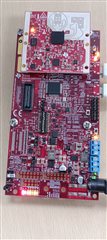
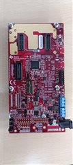
Please find images of board