This thread has been locked.

If you have a related question, please click the "Ask a related question" button in the top right corner. The newly created question will be automatically linked to this question.

TMP61-Q1: TMP6131QLPGMQ1 Component not meeting resistance (RTMP61)

Part Number: TMP61-Q1
Other Parts Discussed in Thread: TMP61

Tool/software:

We have encountered an issue with the resistance of this product.

Out of 3000pcs, we have 852 failed pieces.

The top side marking shows the next code: 2C63F TMP61

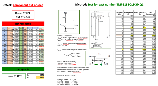
WE built the next circuit:

Rbias = 10,000 ohms (set resistance of clamp)

Vbias = 3.3V (direct voltage)

Rtmp61 = test sensor at temperatures 0 and 70 Celsius degrees.

Vtemp = measured voltage on tested sensor.

Giving us the next formula to calculate the resistance Rtmp61 = (Vtemp*Rbias) / (Vbias-Vtemp)

Calculating this must comply with the resistance value limits taken from the R/T table generated for the TI sensor.

Calculated resistance limit:

R(0°C) = (8441 – 8612) Ω

R(25°C) = (9866 – 10065) Ω

R(70°C) = (12922 – 13183) Ω


Calculated resistance limit: Please help us resolve this issue, as to why they are failing (and not all of them some are good.)

  • Hi Cecilia,

    Your approach in calculating and determining the limits is correct so we should look at the sources of error and double check the setup conditions.

    The first thing I would recommend is to always measure the voltage of the TMP61 by using a DMM or ADC. Contrary to measuring the resistance using an ohmmeter. 

    As for the setup conditions:

    • How is the temperature being forced on the device? Are you using some kind of oil bath or temperature forcing unit? Are you using any temperature references to determine the temperature and are the devices being left soaking for enough time? 
    • How are you measuring the voltage of the device? 
    • Have you tried scoping out the Vsns signal to verify it is not coupling with other sources of noise? 

    Best regards,

    Simon Rojas