This thread has been locked.

If you have a related question, please click the "Ask a related question" button in the top right corner. The newly created question will be automatically linked to this question.

TMAG5273: TMAG5273 - magnetic gain adjustment

Part Number: TMAG5273

Tool/software:

I'm currently working on a project where I want to use the TMAG5273 as an odometer sensor, be measuring the rotations of a wheel axis.
A STM32 uC will be used to connect to the sensor and conduct the measurements. Currently i'm able to connect to the TMAG5273 and readout 
registers with a c++ class i developed. With this I'm able to convert the angle result into a degree format and display it. From my early observations
this works fairly well. I haven't done testing regarding accuracy or sensitivity yet.

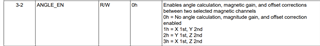
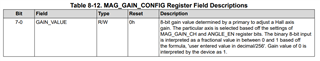
Now i want to implement the magnetic gain adjustment functionality described in chapter 7.2.3.2 of the manual TMAG5273 Low-Power Linear 3D Hall-Effect Sensor With I2 C Interface datasheet (Rev. B).
I don't really understand how the values of the example work and the described process itself and what the adjustment does for the sensor.
As i stated above I'm able to read out the registers I just can't get my head around how the workflow of this function should/can be implemented
in a c++ function, as i don't understand the explanation/example in the manual.

I hope I described my problem understandably and can find support here.

Kind regards
Sebastian

  • Sebastian,

    Welcome to E2E, and thanks for reaching out with your question.  The gain correction is intended to help you set the amplitude of the two axes you are using to the same magnitude.

    You should start by capturing at least a full rotation cycle and look at the amplitudes of your two channels.  You may select either of the two channels used in the angle measurement to adjust.

    Your setting of ANGLE_EN will control this:

    Secondly, the MAG_GAIN_CH will control which axis you will adjust the gain on

    What is meant by first and second channel is noted in your selection of ANGLE_EN.  This axis will be adjusted by the value in MAG_GAIN_CONFIG

    You will identify the larger magnitude of the two axes used in the angle measurement and then select it with MAG_GAIN_CH.  Then take a ratio of:

    (smaller magnitude) / (larger magnitude) to get a value between 0 and 1.  I believe the equation shown may have an error, however.  It currently indicates that you would divide your decimal ratio by 256, but rather it appears that you should multiply this factor by 256.

    Thanks,

    Scott

  • Thanks for the response!

    If i understand correctly, my function should look like this:

    1) Get starting position angle
    2) Start turning the magnet a full 360 degree and readout the X and Y_RESULT_MSB/LSB registers
         until starting position is reached again
    3) Find the highest and lowest values of the respective axis and calculate the amplitude
    4) Compare amplitude and calculate gain adjustment according to the provided formulas and cases
    5) Write value to the MAG_GAIN_CONFIG register and select the axis beforehand

    In consequence to the provided formulas, my gain value would be of type float to get the decimal value.
    I would then multiply his value by 256(as you suggested) and write the result(binary) in the MAG_GAIN_CONFIG register.


    I hope my explanation is understandable and you can verify my thoughts.

    kind regards 
    Sebastian

  • Sebastian,

    This looks to be the correct procedure.

    Thanks,

    Scott