This thread has been locked.

If you have a related question, please click the "Ask a related question" button in the top right corner. The newly created question will be automatically linked to this question.

AWR1843AOPEVM: Radar raw data capturing and MRR

Part Number: AWR1843AOPEVM
Other Parts Discussed in Thread: UNIFLASH, AWR1843AOP

Tool/software:

I am currently working with the AWR1843AOPEVM radar sensor and following the Auto MRR User's Guide. I have successfully flashed the xwr18xx_mrr_demo.bin file located at

C:\ti\radar_toolbox_2_20_00_05\source\ti\examples\ADAS\medium_range_radar\prebuilt_binaries.


Here is the setup I am using:
CCS version: 12.8
SDK version: 3.6
Radar module: AWR1843AOPEVM
UniFlash version: 8.8

I have a few questions on it?

  • After performing flashing and change the mode to functional mode, I ran the application located at "C:\ti\radar_toolbox_2_20_00_05\tools\visualizers\MRR_GUI", but no data n(graphics) is displayed. What could be the issue?

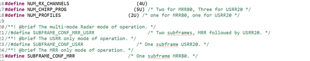
  • Does this MRR is similar to SRR and (just there is change in the Detection range of the radar ) ?
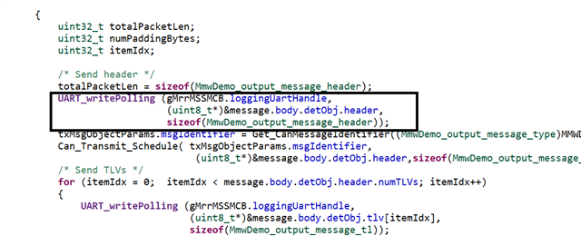
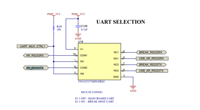
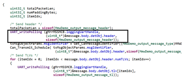
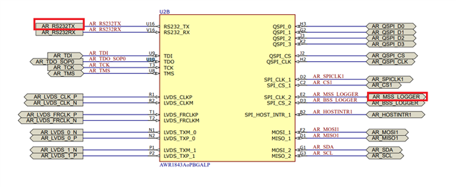
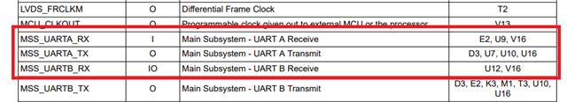
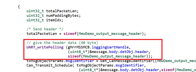
  • I need to capture the raw radar data via UART and transmit it to my controller. Could you guide me on the appropriate connection points on the AWR1843AOPEVM ?

Thanks

Mitesh 

  • Hi,

    It will not be possible to capture raw data with the UART. You will need a DCA1000 capture board to capture raw data.

    The MRR demo is not supported oob on the AOP however you should be able to run it on AOP evm

    First you need to re-build the binaries for MRR mode only

    Please see

    e2e.ti.com/.../awr1843aopevm-running-the-medium-range-radar-on-awr1843aop

    Thank you

    Cesar

  • Hello Cesar,

    Hope you are doing well .

    I followed your suggested link and made changed as per link in the file "mrr_config_consts.h" .Below are the updated code.

    and rebuild the MRR and flashed bin file into the AWR1843AOPEVM and captured the packets through USB port (USB Connector J1) by Realterm app.

    2. I believe I phrased my question incorrectly. My objective is to capture packet data transmitted via UART over USB. However, instead of relying on USB, I want to bypass it and directly send the UART data to my controller.

    Could you advise on the appropriate connection points on the board (using external wiring) to achieve this?

    For reference, I need to capture the following UART data:

    File Name: mss_main.c

    file name:- mss_main.c

  • I need two pairs of UART physical pins, one for configuration and other for data. So how do I do this?

    Please help me locating two TX, two RX physical pins on AWR1843AOPEVM.

  • Hi Mitesh,

    Please refer to the Pin Functions section of the AWR1843AOP datasheet (5.3.1) to show the possible pinouts of MSS_UARTA_TX/RX and MSS_UARTB_TX/RX.

    These pins can then be traced on the AWR1843AOPEVM schematic to locate possible connection points. They may not necessarily be exposed by default.

    Thank you,

    Jin

  • Hello Jin,

    Based on your suggestion, I traced the MSS_UARTA_TX pin and identified it at pin 6 of the TS5A23157QDGSRQ1 (UART selection), labeled as AR_RS232TX.

    I made two connections on the TS5A23157QDGSRQ1 and connected them to the FTDI as follows:

    • AR_RS232TX pin → RX of FTDI
    • Ground pin → Ground of FTDI

    I then attempted to capture data using the RealTerm app. I tested both switch positions (S1.1 OFF and S1.1 ON), but no data appeared in RealTerm.

    Could you confirm if this procedure is correct, or suggest any corrections?


    Thanks 
    Mitesh 

  • Hi Mitesh, 

    I'm looping in a HW expert to advise here. 

    Thank you,

    Jin

  • Thanks for looping in the HW expert.

    Looking forward to their insights.

  • Hi Mitesh,

    In terms of Hardware, all you need is a RX to TX connection of the AWR and TX to RX of the Radar. As long as you have these and the correct SOP mode selected, you should be able to flash. Could you also confirm if S1.2 is ON (pulled high). 

    Could you check if FTDI adapter is configured for 3.3V logic. If the FTDI is outputting 5V, it won't work, you'd need to level shift.

    Just checking, FTDI drivers are installed? Does your com port show up? 

    Regards,

    Aydin 

  • Hello Aydin Kiasat,

    I attempted to capture the packet data by connecting FTDI TX and RX to pins 10 and 6 of the TS5A23157QDGSRQ1. The FTDI was configured for 3.3V logic, and the COM port was detected in the Device Manager.

    I tested all possible switch positions for S1.1 and S1.2 (both ON, both OFF, one ON and the other OFF), but no data packets were received.

    Am I missing something? Please let me know

    Regards,

    Mitesh

  • Hi Mitesh,

    Hardware connection seems to be fine with your description. In flashing mode, could you probe at TX and RX of the Radar and share a scope shot? you could probe at TP18/19. 

    Regards,

    Aydin

  • Hi cesar/Jin,

    Which pin of the AWR1843AOP transmits data via UART, as specified in the code written in mss_main.c? for your reference below snap of code.


  • Hello Aydin ,

    I was able to flash the bin file by connecting the FTDI to TP18/19. However, I am not receiving any radar data in the RealTerm app through TP18/19.

    The AWR1843AOP datasheet (section 5.3.1) lists multiple pins configured as MSS_UARTA_TX/RX and MSS_UARTB_TX/RX.

    Could you please confirm which pin the following code (written in mss_main.c) uses to transmit data through UART?


  • Hi Mitesh, 

    The demo transmits data over UART B.

    We can find this by tracing back the loggingUartHandle.

    In mss_main (1266):

    gMrrMSSMCB.loggingUartHandle = UART_open(1, &uartParams);

    This opens the UART indexed at UART_config[1] defined in ti/drivers/uart/platform/uart_xwr18xx.c, which corresponds to UART B.

    Please note that UART A is used in the demo for commands. Further modifications (e.g. swapping UART A/UART B handles) would be needed to use it for data. 

    Thank you,

    Jin