This thread has been locked.

If you have a related question, please click the "Ask a related question" button in the top right corner. The newly created question will be automatically linked to this question.

AWR1843: Facing issue with Serial Flash through UART

Part Number: AWR1843
Other Parts Discussed in Thread: UNIFLASH,

Tool/software:

Dear TI Team,
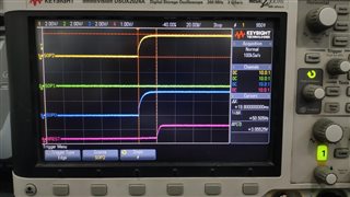
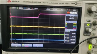
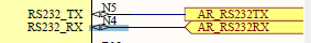
We are encountering a flashing issue on the AWR1843ABL, specifically on Pins N5 (RS232_TX) and N4 (RS232_RX)
 
We are using a USB to UART ( connection of TX ,RX, GND)module for flashing with UNIFLASH software, .but we receive the following error messages, and the flashing does not start:
[ERROR] Cortex_R4_0: XXXX Received unexpected data!!!XXXX
[2/4/2025, 3:05:48 PM] [ERROR] Cortex_R4_0: Not able to connect to serial port. Recheck COM port selected and/or permissions.
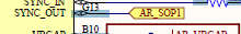
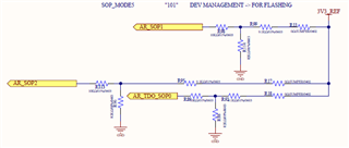
Regarding the AWR1843 boost EVM, we have set the Flash mode to SOP mode 5 ("101"), as described below:
  1. AR_SOP1 to pin G3 
  2. AR_SOP2 to pin P9
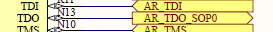
  3. AR_TDO_SOP0 to pin N13 
We are selecting the SOP mode using resistor-based connections (R13, R17, and R18) to provide logic 1 or 0 instead of a switch connection. To achieve this:
  • We opened R13 to set SOP1 = 0 and verified that R98 shows 0V.
  • R13 and R18 were kept as-is to ensure SOP0 and SOP2 were set to logic 1, as per Mode 5.
  • We confirmed 2.8V at R113 and R89 for logic 1.
Before attempting to flash, we performed a power on/off cycle for the AWR module.
I have attached the related schematic to the email; please refer to it, as well as the connector-to-IC pin connections.
Could you kindly assist us in identifying the potential issue and suggest a solution? Additionally, please let us know if we may have missed any steps in the process.
  • Hello,

    Is this a custom board? Can you probe the SOP pins relative to NRESET and share the results? If NRESET is being released before SOP voltages are stable it is possible that the device is being latched in the incorrect SOP mode.

    Also, please share the details on which USB to UART converter you are using.

    Lastly, can you please put the device in SOP2 and probe the XTAL and VBGAP? This is to confirm that the device is powering up correctly. We should see the XTAL running at 40MHz and the VBGAP at 0.9V.

    Regards,

    Adrian

  • Hi,

    1. Yes this is a custom board.

    The waveform attached for SOP PIn and NRST pin in SOP2 mode.

    2. USB to UART Converter : 

    USB-TTL UART Module - CP2102

    3. We probe the XTALP, XYALN, VBGAP and NRST in SOP2 mode. The waveform is attached for your reference.

  • Hello,

    It does not look like VBGAP is coming up to 0.9V and it is hard to tell if XTAL is running because your voltage scale is too large.

    NRESET is also only at 1V, shouldn't it be at 3.3V? If NRESET is not going to 3.3V then the device will be stuck in reset. How is NRESET being controlled?

    Regards,

    Adrian