This thread has been locked.

If you have a related question, please click the "Ask a related question" button in the top right corner. The newly created question will be automatically linked to this question.

IWR6843ISK: The clock drift of IWR 6843ISK

Part Number: IWR6843ISK
Other Parts Discussed in Thread: DCA1000EVM, , MMWAVE-SDK

Tool/software:

Hi TI team,

I am using IWR6843ISK + DCA1000EVM and using mmwave studio to configure every thin.

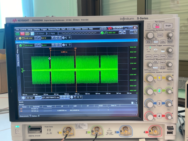
I faced a problem with the clock drift, I used the receiver as well as the down-converter and connected it to the oscilloscope, but seems like the frame periodicity is not exactly the same as the periodicity I set. Also, the frame time drift is also changing with time, for example, the setting is 10ms, but actually, it is 10.00055ms from the oscilloscope, and later it becomes 10.00065ms. And the change of the frame periodicity doesn't change linearly with time. 

So my questions are:

1. Is there any calibration that can help? (I know that by default APLL and VCO Synth run time calibration happens every 1 second) But is there any way to make this calibration for every frame?

2. Is there a model to describe such a clock drift?

3. Are there any workarounds?

Here is my chirp and frame setting, I am not sure if the parameters I am using influence the frame periodicity I mentioned. Interframe time I set is 788 us.

"rlProfiles": [
{
"rlProfileCfg_t": {
"profileId": 0,
"pfVcoSelect": "0x2",
"pfCalLutUpdate": "0x0",
"startFreqConst_GHz": 60.0,
"idleTimeConst_usec": 5.0,
"adcStartTimeConst_usec": 3.0,
"rampEndTime_usec": 20.0,
"txOutPowerBackoffCode": "0x0",
"txPhaseShifter": "0x0",
"freqSlopeConst_MHz_usec": 50.0,
"txStartTime_usec": 0.0,
"numAdcSamples": 212,
"digOutSampleRate": 12500,
"hpfCornerFreq1": 0,
"hpfCornerFreq2": 0,
"rxGain_dB": "0x1E"
}
}
],
"rlChirps": [
{
"rlChirpCfg_t": {
"chirpStartIdx": 0,
"chirpEndIdx": 0,
"profileId": 0,
"startFreqVar_MHz": 0.0,
"freqSlopeVar_KHz_usec": 0.0,
"idleTimeVar_usec": 0.0,
"adcStartTimeVar_usec": 0.0,
"txEnable": "0x1"
}
}}

"rlFrameCfg_t": {
"chirpEndIdx": 1,
"chirpStartIdx": 0,
"numLoops": 222,
"numFrames": 0,
"framePeriodicity_msec": 11.888,
"triggerSelect": 1,
"numDummyChirpsAtEnd": 0,
"frameTriggerDelay": 0.0
}

Best,

Bei

  • Hi Bei, 

    We are looking into your question. Please give us a day or so to respond. 

    Thank you, 

    Josh

  • Hi Bei,

    I am looking into your query. Please allow me a couple of days t o respond back to you.

    Thanks,

    Swarnendu 

  • Hi Bei,

    Could you please share how are you doing the measurements?

    Are you using a different receiver antenna and down-converting the RF signal?

    What are you plotting in oscilloscope, the analog signal?

    Thanks,

    Swarnendu

  • Hello Swarnendu,

    Yes, I am using a different receiver antenna and a downconverter mixed with a 60Ghz signal, so I will get a 0-2GHz signal after the converter. Yes I am plotting analog signal. Something like what the figure is showing.

    Best,

    Bei

  • Hi Bei,

    Understood. 

    Actually, it is not clock-drifting that you are seeing in the event of frame time changing by ~550ns. The Synthesizer and APLL requires some time to re-start. Such high refresh rate (10ms of frame time), and interframe time as low as 788us might not be enough for that, hence, the frame timer will adjust the startup time of the APLL and SYNTH. Therefore, you might see little drift in the frame time. For the device, it is unrealistic to have control over this.

    However, you can disable the SYNTH power down using respective APIs and use an external MCU to trigger the frames with APLL and SYNTH never shutting down. That way you should have full control over the frame time. We don't have specific demo for this. This has to be designed at customer side.

    The runtime calibrations take place every one second and it cannot be modified for each frame. 

    Thanks,

    Swarnendu

  • Hello Swarnendu,

    Thanks a lot for your reply. As you said the issue is because the interframe time I set is low and might not enough for restarting of Synthesizer and APLL, for my case, is there any recommending inter frame time value ? How long will be enough?

    Best,

    Bei

  • Hey Swarnendu,

    Just wanted to follow up on my question about the recommended interframe time to ensure the Synthesizer and APLL restart properly. Do you have any insights on how long would be enough? Thanks in advance.

    Thanks!
    Bei 

  • Hi Bei,

    Sorry for the delay in response.

    I would like you to please refer to the below document for the timing requirements for chirp programming.

    https://www.ti.com/lit/an/swra553a/swra553a.pdf 

    I would also like you to refer to the mmWave-SDK Doxygen, which can be found in the below location:

    <mmWave_SDK_Installation_Path>\packages\ti\demo\<Device Name>\mmw\docs\doxygen\html\index.html  

    Lastly, please refer to the mmWave sensing estimator: 

    https://dev.ti.com/gallery/view/mmwave/mmWaveSensingEstimator/ver/2.4.0/ 

    Thanks,

    Swarnendu

  • Hello Swarnendu,

    From the manual the timing requirements for chirp programming.

    The timing requirements for the advanced frame is as follows: Inter-burst time should be ≥ 50 µsec, inter sub-frame time should be ≥ 100 µsec and inter frame time should be ≥ 200 µsec. 

    788 us should be enough according to the chirp programming manual.

    I think mmWave-SDK Doxygen is mainly for standalone radar use cases, but I am using a data capture board as well. So in the mmWave-SDK Doxygen, it considers the 2D/3D processing time , but I don't think that I need to consider the data processing time in my case. 

    So Honestly I don't know what value should I set now to avoid the little drift I observed in the frame time. Would appreciate it if you can suggest something

    Best,

    Bei

  • Hi Bei,

    In your configuration, do you have inter-frame idle time 788us?

    Is this number coming from calculation or from the analog signal waveform observation?

    As you are observing the signal after down-converting it, what is the accuracy of the down-converter?

    Also, could you please share a snap-shot of the analog signal you are receiving? I cannot see the previous image clearly for the low resolution.

    Thanks,

    Swarnendu

  • Hi Swarnendu,

    Sorry for the late reply.

    Yes, the inter-frame idle time is 788µs, and this value comes from calculation—I didn't directly verify it from the analog signal waveform.

    I believe the timing should be quite accurate since we use it extensively for 60GHz experiments. I’m currently checking the specification and will get back to you once I have it.  Also, I’m rather certain the issue stems from the radar itself. I tested with two radars operating at the same frame period, positioned in front of each other. If the frames were truly synchronized, the interference signal from one radar should appear in the same chirp for each frame of the other. However, I observed the interference signal showing up in different chirps, which suggests some frame period inaccuracy from the radar.

    Attached is the figure you requested, hope this is more clear now.

    Best,
    Bei

  • Hello Bei,

    Thanks for sharing the image.

    Observing parallel interference with LOs not synced together would have multiple differences between them. Hence, it could be difficult and might not provide absolute confirmation of frame time delay.

    In the scope I am seeing 11.889ms which is similar to the frame time that has been set in the configuration (11.888ms).  

    Ideally the frame time error will depend on the XTAL ppm error. The 40MHz crystal that has been used in IWR6843ISK has a tolerance of +/-50ppm. With this, a ~0.5us drift for a 10ms frame period is expected. This is not arising from the chirp, rather this is because of the frequency tolerance of the XTAL.

    Thanks,

    Swarnendu

  • Hi Swarnendu,

    Thanks a lot for your explanation, it is helpful indeed. 

    Though I have a few follow-up questions. 

    1. I observed that the frame periodicity is 11.8886624ms after it runs for some time, so it is a little bit higher than the +/-50ppm range you said. So is there any other factor that influences the XTAL ppm tolerance, like temperature? Or the error will generally become higher after the device has been running for some time?

    2. Does the ppm error change with time? Because from what I observed, every frame has a little bit of error from the set number, but the error is also different from frame to frame. Is that a normal phenomenon?

    3. Is there any way to calibrate? (From my understanding, I cannot)

    Thanks in advance!

    Best,

    Bei

  • Hello Bei,

    Please find my responses below:

    1. In the configuration you have shared, the frame time is set to 11.888ms. Could you confirm it?

    2. The XTAL frequency tolerance is +/-50ppm and frequency stability is +/-200ppm. These are maximum limits. The error will be within this limit.

    Thanks,

    Swarnendu

  • Hi Swarnendu,

    1. Correct.

    The error is different for different XTAL, right? But does the ppm error change with time for a specific radar?

    Regarding XTAL, there is nothing we can calibrate, right?

    Best,

    Bei

  • Hello Bei,

    With time, considering few frames, ideally it should not change beyond the specified limit. Also, it is not dependent on the radar device. The necessary drive strength, load capacitance and other parameters are usually taken care of while selecting the XTAL. Considering radar applications, we generally allow +/-50ppm frequency tolerance.

    Across temperature the frequency of XTAL varies within +/-200ppm. It may so happen that with time as the radar device chirps and gets heated up few degrees C, you are observing a slightly more drift.

    Yes, the XTAL tolerance is something we cannot get rid of. 

    Thanks and regards,

    Swarnendu

  • Hi Swarnendu,

    Thanks a lot for your reply. It is quite helpful.

    Best,

    Bei

  • Thanks Bei. 

    Glad to help.

    Regards,

    Swarnendu