This thread has been locked.

If you have a related question, please click the "Ask a related question" button in the top right corner. The newly created question will be automatically linked to this question.

DRV401: SOME QUESTIONS RELATED TO PROBE COIL AND COMPENSATION COIL?

Part Number: DRV401
Other Parts Discussed in Thread: DRV411

Tool/software:

Hi E2E experts,

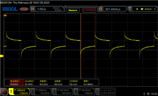
I am trying to use DRV401 in my new design, but I meet a problem, hope to get your kindly suggestion.When I used Iron based nanocrystalline annular magnetic core to be the probe coil,it seems to be excessive inductance,which means there just a little number of windings such as 11 turns。 Therefore, I  wonder if the probe coil 's farmework can be just a plastic shell? but its excitation current wave didn't have right duty cycle as followed

but if the probe coil 's framework have magneticcores

:

here is my question:

1. Is this structure feasible?

2.Is there some relation between probe coil and compensaion coil?

3. how to set compensation coil windings? for example, i want to measure high frequency 6A current and I just set 24 turns for compensation coil as CT?Is same to low frequency?

4.as mannual, probe coil frequency just work at 250kHz to 550kHz , I wonder if the probe coil can work at lower frenquency such as 100kHz to 200kHz?

Looking forward for your reply. Thank you very much!

Yours sincerely,

Caleb

  • Hello Caleb, 

    Thank you for your post.

    Here are my responses to your questions:

    1. The probe coil as you drew will not sense the magnetic field that the flux-gate front-end requires. You will need to have an air gap in your magnetic core to place the field probe inside of the magnetic core:
    2. This is a closed loop system so the best way to say this is the field probe senses the magnetic field induced by the primary winding through the core, then the DRV401 drives the compensation coil to induce a magnetic field in the opposite direction bringing the flux at the sensor to 0. Please see this E2E post for more information on the DRV401: (+) DRV411: Accurate Magnetic Field sensing up to 15mT - Amplifiers forum - Amplifiers - TI E2E support forums
    3. Yes you are correct that you would need 24 turns on the compensation coil in theory. If the inductance of your compensation coil is too high then you can consider implementing an external buffer as shown in this reference design using the DRV411: https://www.ti.com/lit/ug/tidu820/tidu820.pdf 
    4. Our minimum oscillation frequency for the probe loop is 250kHz.
      1. At lower frequencies, I would be concerned about the probe not reaching saturation. Can you share the inductance and resistance of the probe winding you are using?

    I hope this helps, 

    Joe