This thread has been locked.

If you have a related question, please click the "Ask a related question" button in the top right corner. The newly created question will be automatically linked to this question.

IWRL6432: Ragarding start frequency

Part Number: IWRL6432
Other Parts Discussed in Thread: IWR6843

Tool/software:

Hi team,

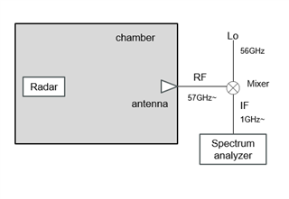
We are trying to measure the Tx start frequncy on our IWRL6432 custom board.
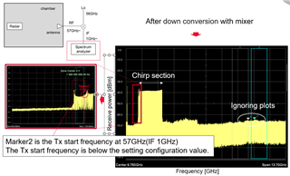
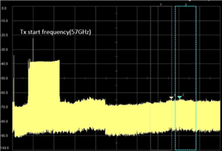
The Tx start frequency is being RF output from below the setting configuration value.
Please tell me why this happens that.

best regards,
Masaya.

  • Hi Masaya,

    Please allow us a couple of days to respond back to you.

    Thanks,

    Swarnendu

  • Hi Swarnendu,

    Thank you for letting me know. I appreciate your prompt communication and will look forward to hearing back from you.

    Best regards,

    Masaya

  • Hi Masaya,

    To inspect further, I would require some more details on the issue.

    Could you please share the below details?

    1. What is the experiment set up?

    2. What configuration is being used?

    3. What does the plot signify? 

    Thanks

    Swarnendu

  • Hi Swarnendu,

    1. What is the experiment set up?
    we are  useing the folowing measurement system:

    2. What configuration is being used?

    sensorStop 0
    channelCfg 7 3 0
    chirpComnCfg 28 0 0 256 4 80 1
    chirpTimingCfg 6 12 0 25 57.0
    frameCfg 2 0 390.35 64 100 0
    antGeometryCfg 0 1 1 2 0 3 0 0 1 1 0 2 2.4 2.4
    guiMonitor 2 1 0 0 0 1 0 0 0 0 0
    sigProcChainCfg 32 4 1 1 4 4 0 20
    cfarCfg 2 8 4 3 0 15.0 1 0.5 0 1 0 1
    aoaFovCfg -10 10 0 0
    rangeSelCfg 8.1 8.5
    clutterRemoval 0
    compRangeBiasAndRxChanPhase 0.0 1.00000 0.00000 -1.00000 0.00000 1.00000 0.00000 -1.00000 0.00000 1.00000 0.00000 -1.00000 0.00000
    adcDataSource 0 C:/ti/mmwave_lp_sdk/examples/datapath/common/testBench/major_motion/adc_data_0001_CtestAdc6Ant.bin
    adcLogging 0
    lowPowerCfg 0
    factoryCalibCfg 0 1 30 0 0x1ff000
    runtimeCalCfg 0 0 0 0 0 0 0
    clusterCfg 1 0.5 1
    baudRate 1250000
    sensorStart 0 0 0 0

    3. What does the plot signify? 

    Why this happens that?

    Best regards,

    Masaya

  • Masaya,

    Thanks for sharing the details. If my understanding is correct, the IF is expected to be 1GHz and above (based on the 2GHz BW), but in the spectrum analyzer below 1GHz is detected. Could you please confirm this?

    I would like to ask the tolerance of the 56GHz LO. How accurate is the LO signal generator?

    Also, is it possible to directly measure the RF frequency? I understand if the spectrum analyzer does not have enough bandwidth.

    Technically Radar device cannot transmit below 57GHz. Therefore, I am more skeptical on the LO and the down converter accuracy.

    Thanks,

    Swarnendu

  • Hi Swarnendu,

    Thank you for your response.
    >>If my understanding is correct, the IF is expected to be 1GHz and above (based on the 2GHz BW), but in the spectrum analyzer below 1GHz is detected. Could you please confirm this?
    Yes, your understanding is correct.

    We also check other chip IWR6843 is no problem, it is working RF output at the desired frequency.   
    So, we think that LO tolerance is no plobrem.

    Please check if the 6432 is outputting at a frequency lower than 57GHz.

    Best regards,

    Masaya

  • Hi Masaya,

    IWRL6432 should not transmit lower than 57GHz. I would have below questions:

    1. What is the chirp configuration you are using?

    2. Are you measuring in TI EVM or custom antenna? If this is with custom antenna, could you please try with TI EVM and confirm if you have similar observation?

    3. In case of custom antenna, what is the bandwidth the antenna is tuned to?

    4. Are you also seeing drift in start frequency if the start frequency is set to higher than 57GHz?

    Thanks,

    Swarnendu